
Automatic Network Discovery In Precision Time Protocol Networks

Active Publication Date: 2015-05-21
ROCKWELL AUTOMATION TECH
View PDF8 Cites 10 Cited by
  • Summary
  • Abstract
  • Description
  • Claims
  • Application Information

AI Technical Summary

Benefits of technology

The invention is about using existing protocols to create a visual network map that can help identify errors and improve network design. This can be useful for debugging and replacing parts of a network. The invention also makes it easier to connect devices and ensures that they are connected correctly. The visual network map can also help with visual support during maintenance and debugging. Overall, the invention reduces debugging time, simplifies network design, and improves visualization for better technical support.

Problems solved by technology

However, implementation of such networks typically requires implementation of specialized hardware in the nodes.
Consequently, nodes not having such specialized hardware, such as legacy nodes, are typically not supported.
However, such systems are typically limited by their configurations and therefore lack flexibility.

Method used


Image

  • Automatic Network Discovery In Precision Time Protocol Networks
  • Automatic Network Discovery In Precision Time Protocol Networks
  • Automatic Network Discovery In Precision Time Protocol Networks

Examples


Embodiment Construction

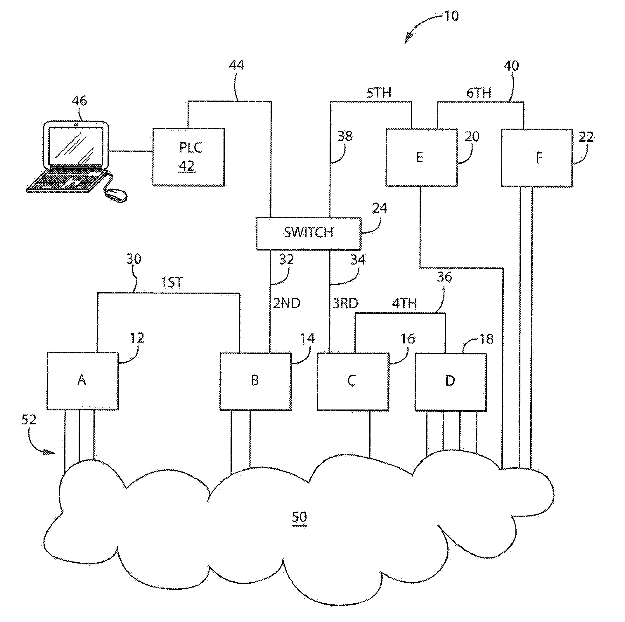
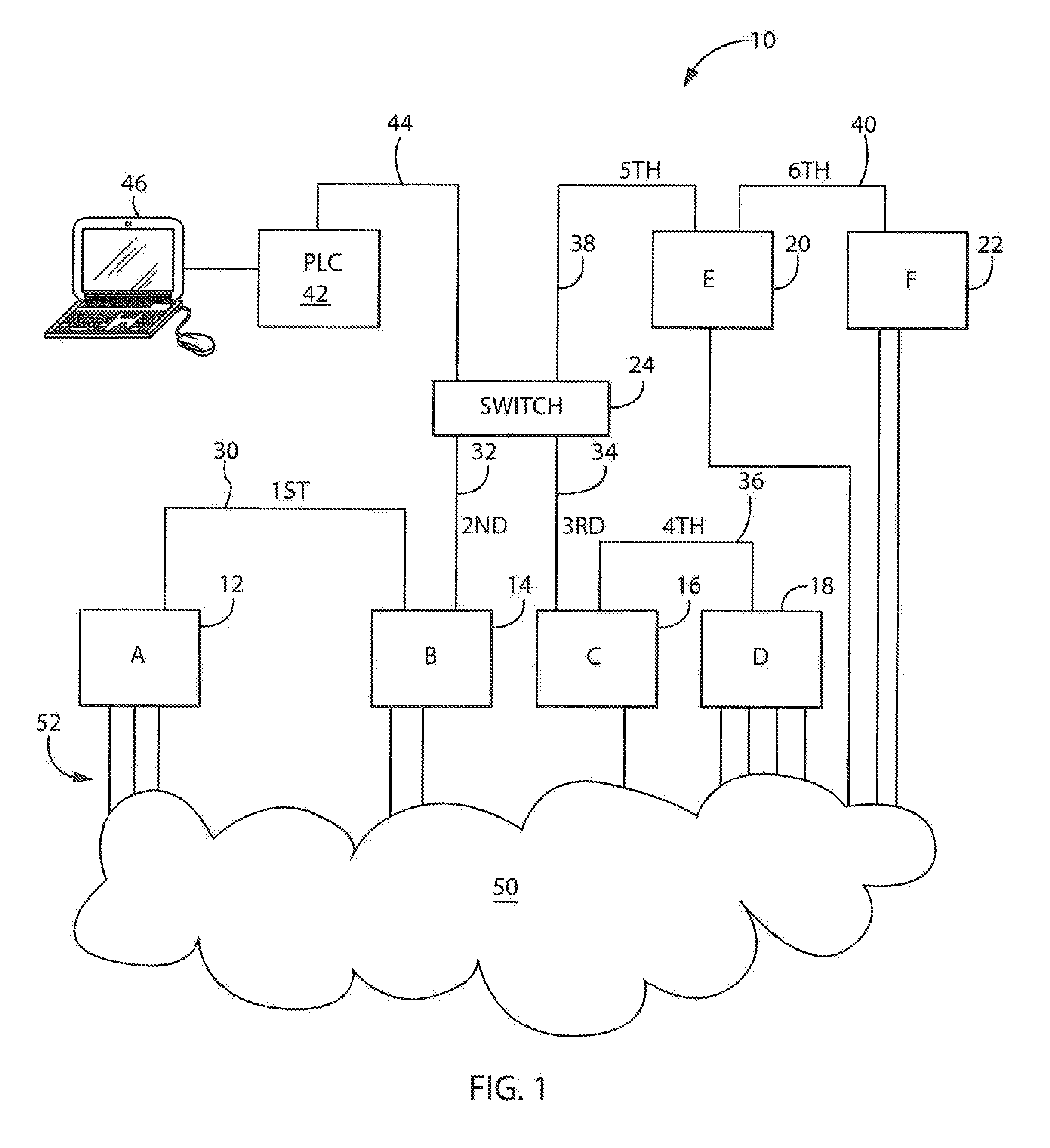
[0040]Referring now to FIG. 1, an exemplar system diagram comprising an arrangement of nodes configured in a computer network in accordance with an embodiment of the invention is provided. An industrial control system 10 includes a computer network having an arrangement of nodes 12, 14, 16, 18, 20 and 22, labeled A, B. C, D, E and F, respectively. Each node A, B, C, D, E and F includes networking functionality at both a physical layer and a logical layer, and each node may communicate with other nodes on the network accordingly. Node A may be, for example, a converter that receives AC power and provides DC power to other nodes in the network, and nodes B, C, D, E and F may be, for example, drives requiring varying amounts of DC power delivery from node A.

[0041]By way of example, a first port of Node A is connected to a first port of node B via a first network segment 30, and a second port of node B is connected to a first port of a multi-port network switch 24 via a second network s...


PUM


Abstract

Aspects of the present invention provide systems and methods using precise timing relationships between nodes in computer networks to generate mappings depicting the physical arrangement or ordering of nodes in the computer networks. The technical effect is by tracking the timing delays between nodes as observed by an individual node, and collecting such information together for subsequent processing, nodes may receive and / or construct an entire physical network topology using an algorithm accordingly.

Description

BACKGROUND OF THE INVENTION[0001]The present invention relates to the field of computer networks, and, in particular, to systems and methods for analyzing computer networks.[0002]Computer networks, such as Institute of Electrical and Electronics Engineers (IEEE) 802.3 Ethernet networks and Ethernet / IP networks, are typically implemented via multiple connected nodes. Each node on the network often includes networking functionality at both a physical layer and a logical layer, and each node may be aware of and communicate with other nodes on the network. As a result, various nodes may be used to carry out particular functions in the computer network, whether alone or in combination with other nodes, such as nodes that are AC Servo Drives implementing I / O functionality as part of an industrial control system.[0003]In such computer networks, multiple connected nodes may also be connected to other multiple connected nodes via switches, routers, gateways, hubs and / or other devices. Accord...

Claims


Application Information

Patent Timeline
IPC IPC(8): H04L12/24H04L12/26
CPCH04L41/0853H04L43/18H04L41/12H04L43/106H04L45/18H04L45/48Y04S40/00
Inventor RIEDERER, KEVIN J.NAGEL, GERRY M.SAWANT, MANAS
Owner ROCKWELL AUTOMATION TECH
Learn More