
Signal conversion in communications satellites

a technology of communications satellites and signals, applied in the field of signal conversion in communications satellites, can solve the problems of large switch matrixes, large switch matrixes, and large payload of satellites, and achieve the effect of reducing phase nois

Active Publication Date: 2015-05-21
AIRBUS DEFENCE & SPACE
View PDF17 Cites 11 Cited by
  • Summary
  • Abstract
  • Description
  • Claims
  • Application Information

AI Technical Summary

Benefits of technology

The present invention provides an apparatus and system for use in a communications satellite to select signals from a multiplexed signal received in an input frequency range. The apparatus includes a mixer, a bandpass filter, and a second mixer to downconvert the signal to a different frequency range. The system includes multiple frequency-conversion modules, amplifiers, and an output stage to flexibly route signals to different downlink beams. The system also includes a flexible frequency-reuse module to change the frequency reuse pattern of the downlink beams. The technical effects of the invention include reducing phase noise, flexible routing of signals, and improved signal quality.

Problems solved by technology

However, the digital signal processing systems are not suitable for use at large bandwidths.
Such switch matrixes are large and add significant mass to the payload of the satellite, and become impractical when there are a large number of ports, for example a large number of downlink (user) beams to be formed.
These systems suffer from relatively high phase noise due to the use of several local oscillator LO signals.

Method used


Image

  • Signal conversion in communications satellites
  • Signal conversion in communications satellites
  • Signal conversion in communications satellites

Examples


Embodiment Construction

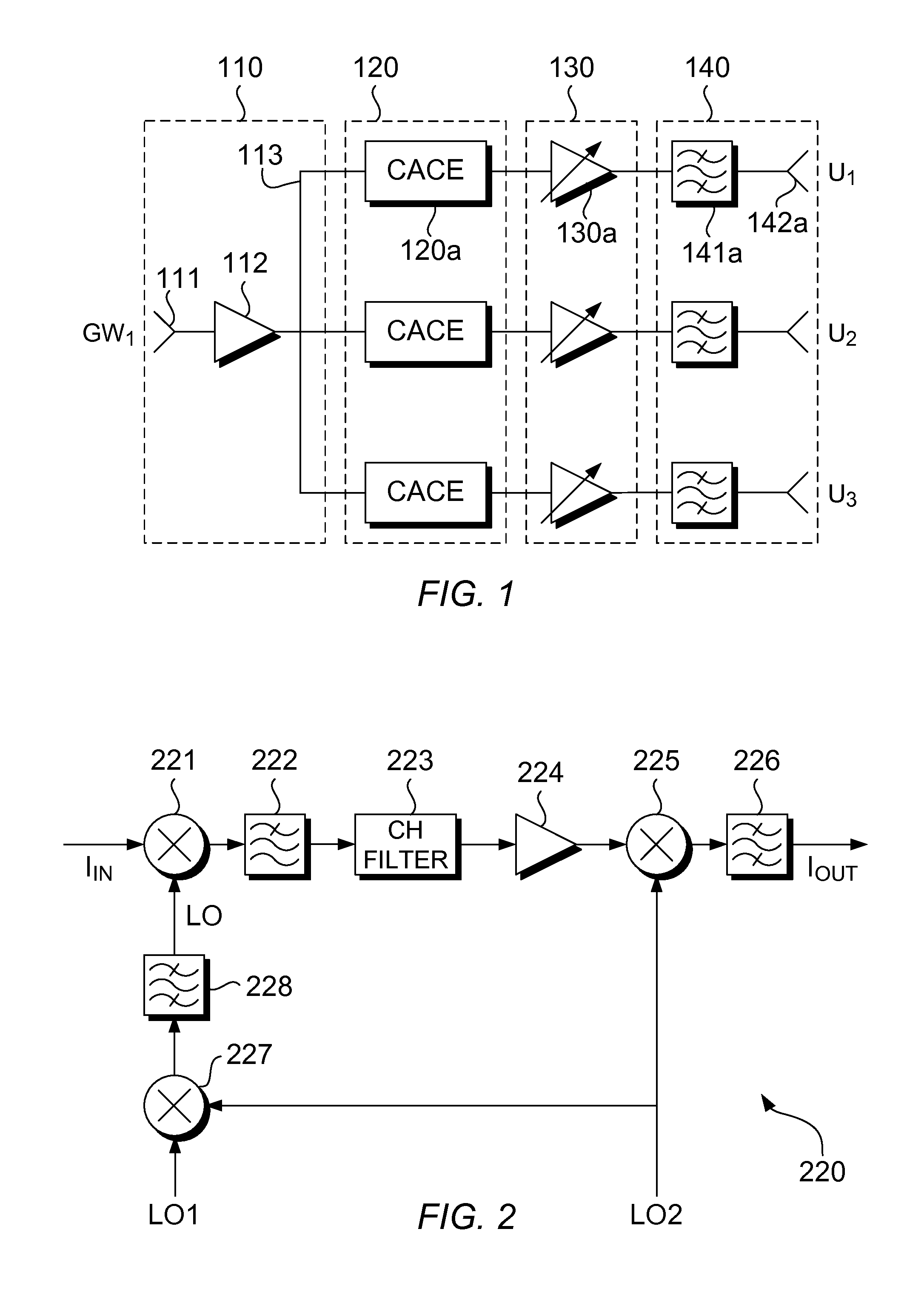
[0030]Referring now to FIG. 1, a system for routing signals from a received multiplexed signal to a plurality of downlink beams in a communications satellite is illustrated, according to an embodiment of the present invention. The system shown in FIG. 1 is provided for illustrative purposes only, and has been simplified so as not to obscure the principles of the invention.

[0031]The system comprises an input stage 110, a signal-converting stage 120, an amplifying stage 130, and an output stage 140. The input stage 110 comprises an antenna 111 connected to a low-noise amplifier (LNA) 112. The antenna 111 is arranged to receive an uplink signal, for example from a ground-based transmitter of a service provider. In the present example, the received signal is a gateway signal GW1 received from a gateway. The received signal GW1 is a multiplexed signal including signals across a large frequency range, and may be referred to as a broadband signal. The LNA 112 amplifies the received signal,...


PUM


Abstract

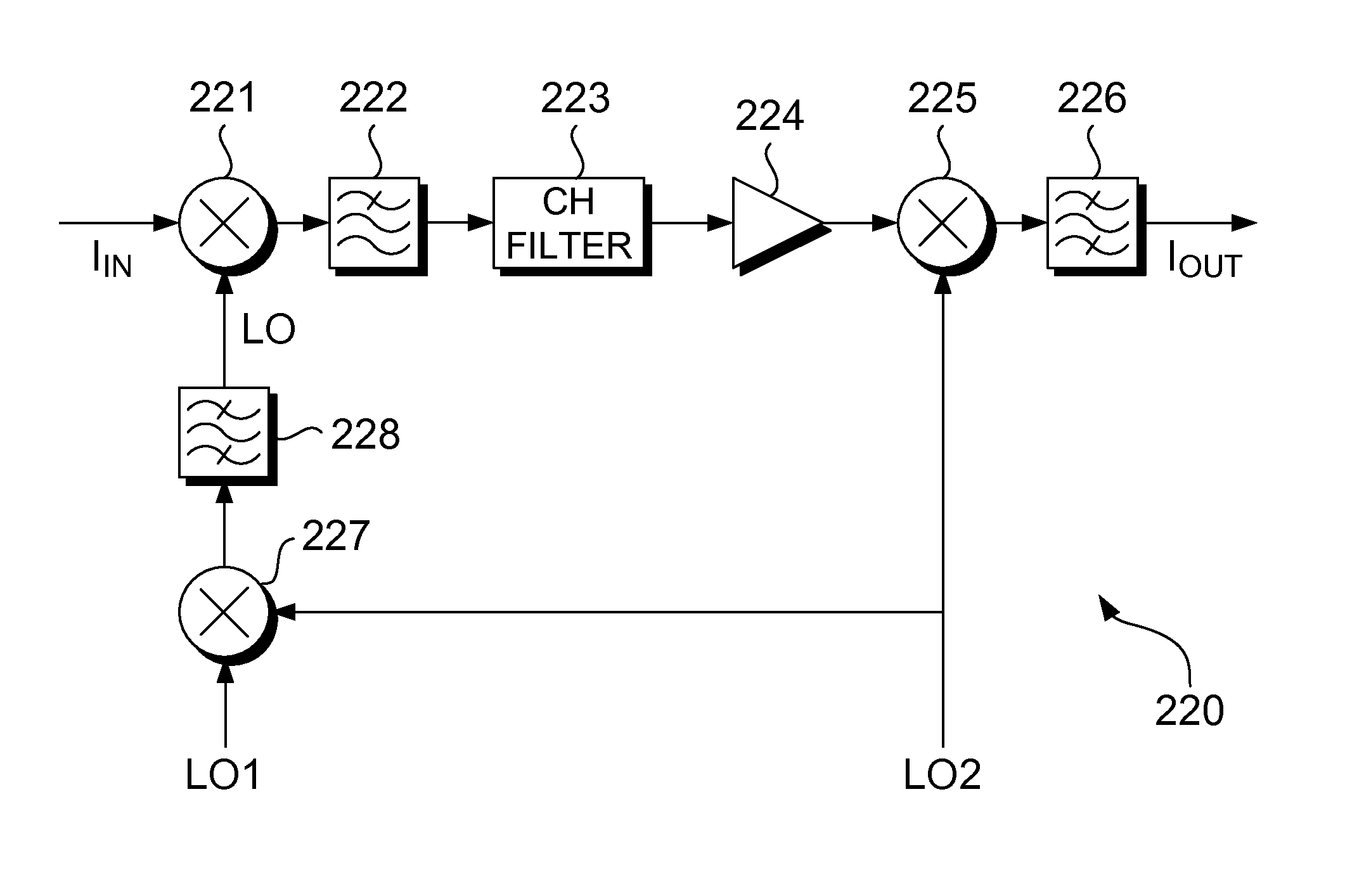
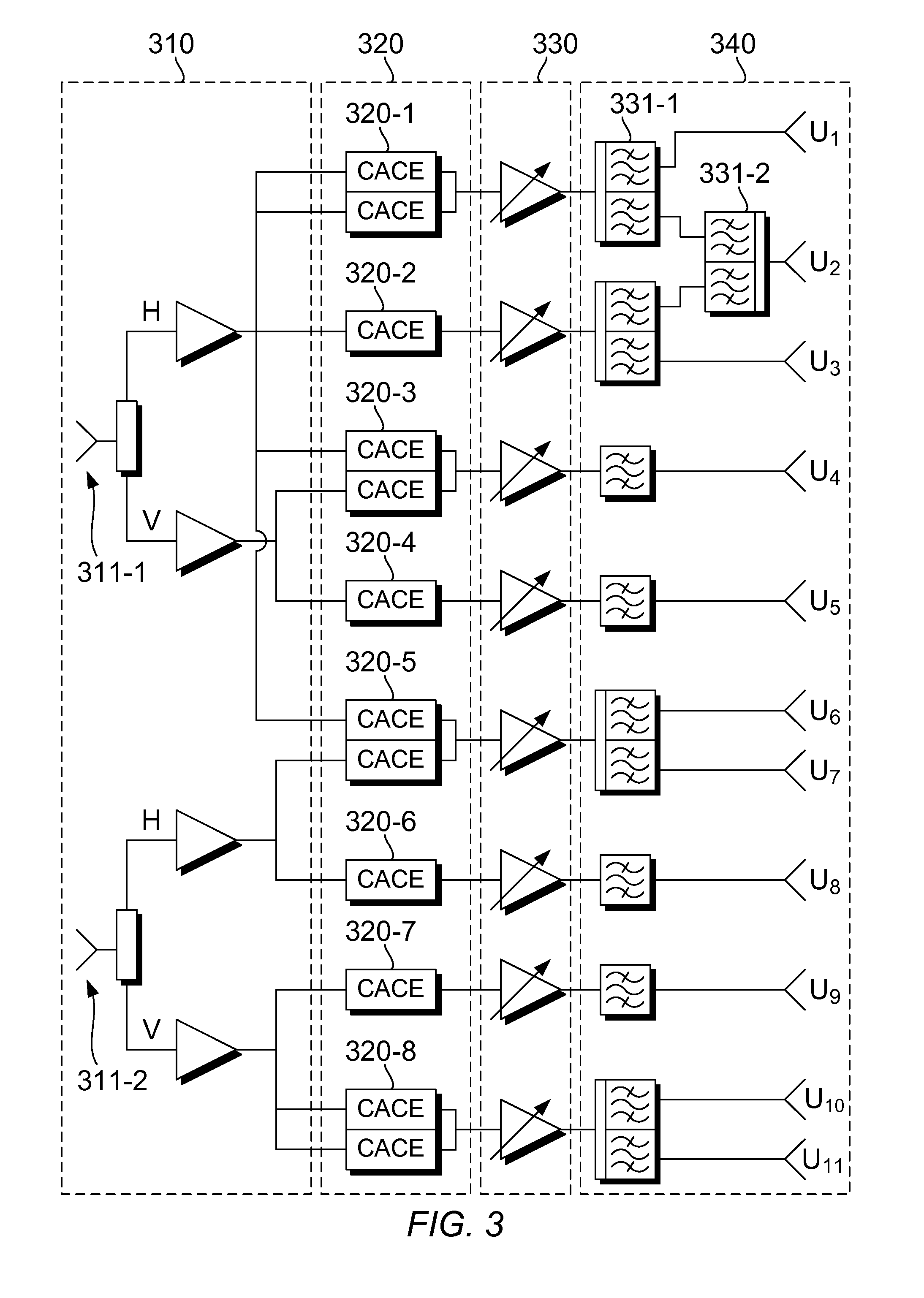
Apparatus for use in a communications satellite to select signals in a first frequency range from a received multiplexed signal comprises a first mixer arranged to mix the received signal with a first local oscillator LO signal to down-convert the received signal so that a signal within the received signal at a centre frequency of the first frequency range is converted to an intermediate frequency IF, a bandpass filter arranged to filter the mixed signal such that the filter bandwidth defines the width of the first frequency range, the bandpass filter having a passband with a centre frequency at the IF, and a second mixer arranged to mix the filtered IF signal with a second LO signal to up-convert the IF signal to the output frequency range. One of the first and second LO signals is a mixed LO signal obtained by mixing the other one of the first and second LO signals with a third LO signal, and the output frequency range is different to an input frequency range in which the multiplexed signal was received. The first LO signal is controllable to change the frequency that is converted to the intermediate frequency by the mixer, to select a different frequency range as the first frequency range. A system is also disclosed for flexibly routing signals in a communications satellite. The system comprises an input arranged to send the received signal to each one of a plurality of frequency-conversion modules comprising the apparatus, a plurality of amplifiers for amplifying converted signals outputted by the frequency-conversion modules, and an output module arranged to receive the amplified signals and form a plurality of downlink beams, each downlink beam including one or more of the amplified converted signals. The amplifiers can be variable-power amplifiers to amplify each converted signal to a transmit power according to the bandwidth occupancy. The system can be used in forward or return path payloads.

Description

FIELD OF THE INVENTION[0001]The present invention relates to converting signals in a communications satellite. In particular, the present invention relates to down-converting a received signal to an intermediate frequency IF using a first local oscillator LO signal, filtering the IF signal to select signals within the received signal, and up-converting the filtered signal to an output frequency using a second LO signal, one of the first and second LO signals being a mixed LO signal obtained by mixing the other one of the first and second LO signals with a third LO signal.BACKGROUND OF THE INVENTION[0002]Communications satellites can be arranged to use different frequency bands for transmission and reception to avoid interference between incoming and outgoing signals. In this case, signals received in the uplink band must be converted to an appropriate frequency in the downlink band before they are transmitted. In digital systems, received analogue signals are converted into the digi...

Claims


Application Information

Patent Timeline
Patent Type & Authority Applications(United States)
IPC IPC(8): H04B7/185
CPCH04B7/18515H04B7/18584H04B1/28
Inventor SAHA, MRINALPORECKI, NICOLAIRANI, SHAHTHOMAS, GLYN
Owner AIRBUS DEFENCE & SPACE
Learn More