Run-in coating based on metal fibers

Active Publication Date: 2015-05-21
MTU AERO ENGINES GMBH
View PDF11 Cites 0 Cited by
  • Summary
  • Abstract
  • Description
  • Claims
  • Application Information

AI Technical Summary

Benefits of technology

[0011]The invention proposes, for a run-in coating, instead of the metal scaffold made of a metal foam as known in the prior art, to provide a metal scaffold which is not formed from a foam but from metal fibers. It is thus possible both to simplify production and to imp

Problems solved by technology

However, such materials and, respectively, seals or run-in coatings are in part expensive and difficult to produce, and also the property profile, with respect to a sealing structure with sufficient strength but at the same time as little re

Method used


Image

  • Run-in coating based on metal fibers
  • Run-in coating based on metal fibers

Examples


Example

[0022]The particulars shown herein are by way of example and for purposes of illustrative discussion of the embodiments of the present invention only and are presented in the cause of providing what is believed to be the most useful and readily understood description of the principles and conceptual aspects of the present invention. In this regard, no attempt is made to show details of the present invention in more detail than is necessary for the fundamental understanding of the present invention, the description in combination with the drawings making apparent to those of skill in the art how the several forms of the present invention may be embodied in practice.

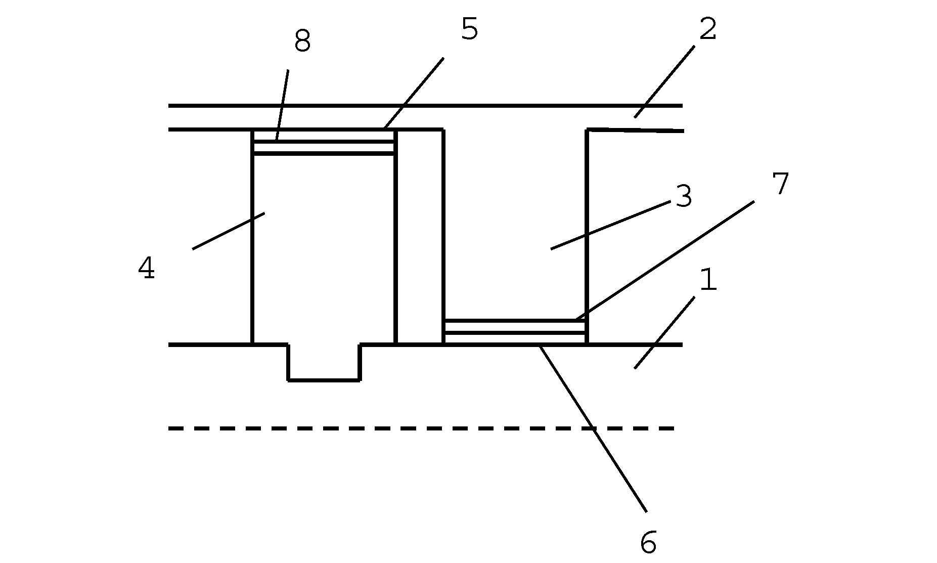
[0023]FIG. 1 shows a partial section through a turbomachine such as an aero engine, having a shaft 1 which is surrounded in annular fashion by a casing 2, wherein however FIG. 1 shows only one part above the line of symmetry or axis of rotation, which is represented by a dashed line. A multiplicity of rotor blades 4 are ar...


PUM


Abstract

The present invention relates to a run-in coating for a turbomachine, in particular for an aero engine, to be attached to a seal between a rotor and a stator, wherein the run-in coating comprises a metallic scaffold having interstices which are filled with an inorganic-nonmetallic filler material, and wherein the metallic scaffold is formed from an arrangement of metal fibers (9). The invention also relates to a corresponding turbomachine.

Description

CROSS-REFERENCE TO RELATED APPLICATIONS[0001]The present application claims priority under 35 U.S.C. §119 of German Patent Application No. 102013223585.2, filed Nov. 19, 2013, the entire disclosure of which is expressly incorporated by reference herein.BACKGROUND OF THE INVENTION[0002]1. Field of the Invention[0003]The present invention relates to a run-in coating for a turbomachine, in particular an aero engine, to be attached to a seal between a rotor and a stator, wherein the run-in coating comprises a metallic scaffold having interstices which are filled with an inorganic-nonmetallic filler material.[0004]2. Discussion of Background Information[0005]In turbomachines, such as static gas turbines or aero engines, a rotor in the form of a rotating shaft having a multiplicity of rotor blades rotates with respect to a stator which is formed by the surrounding casing and guide vanes arranged thereon. In order to achieve a high degree of efficiency, all the working gas flowing through ...

Claims


Application Information

Patent Timeline
IPC IPC(8): F01D11/00F01D5/02F01D9/02
CPCF01D11/001F05D2240/55F01D5/02F01D9/02F01D11/02F01D11/125F05D2300/614Y10T442/2926Y02T50/60
Inventor WERNER, ANDREANDERSEN, OLAFHAUSER, RALFKOSTMANN, CRIS
Owner MTU AERO ENGINES GMBH
Why Eureka
Try Eureka