
Glass container comprising a glass bottom with improved properties

Pending Publication Date: 2021-06-24
SCHOTT PHARMA AG & CO KGAA +1
View PDF0 Cites 0 Cited by
  • Summary
  • Abstract
  • Description
  • Claims
  • Application Information

AI Technical Summary

Benefits of technology

The present invention is about a process for making glass containers with a specific shape that make them easier to inspect and fill. This is achieved by using a separation gas burner that moves along the glass tube during the separation process. This results in a more desirable bottom geometry that is easier to inspect, and this shape can be achieved without using fixed separation gas burners. By adjusting the outer contour of the bottom of the glass container, the optical inspection capability is significantly improved. Overall, this process simplifies the production of vials and allows for improved quality control.

Problems solved by technology

It has been observed that state of the art glass containers, particularly the state of art pharmaceutical vials that have been prepared by means of the conventional process as described above can often only be inspected optically through the glass bottom to an insufficient extent in an optical inspection machine.
The reason for this limited inspection capability is—in addition to the lens effect of the glass bottom caused by the bottom indentation—a non-uniform structure of the outer surface of the glass bottom, which leads to undesired light refracting effects.
As a consequence of these light refracting effects a large number of results cannot be interpreted by these inspection machines and the corresponding glass containers are therefore ejected from the automated process.

Method used


Image

  • Glass container comprising a glass bottom with improved properties
  • Glass container comprising a glass bottom with improved properties
  • Glass container comprising a glass bottom with improved properties

Examples


Embodiment Construction

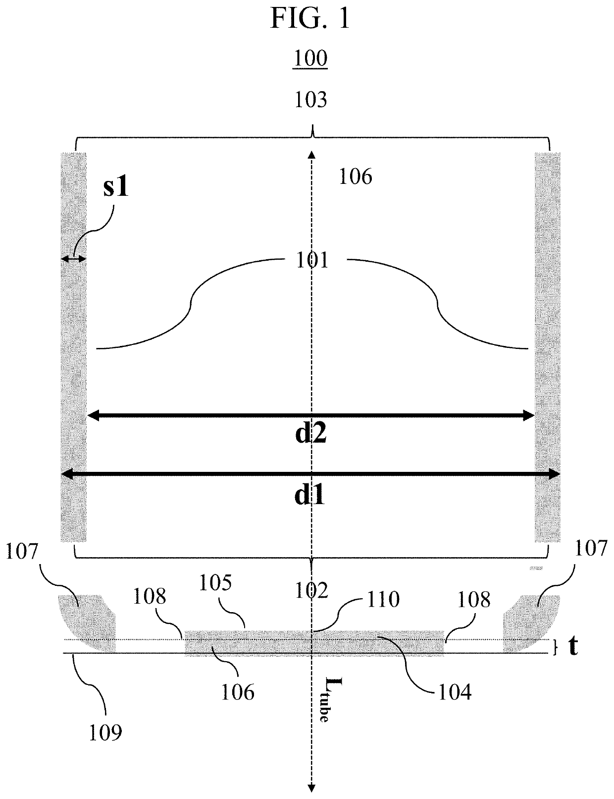
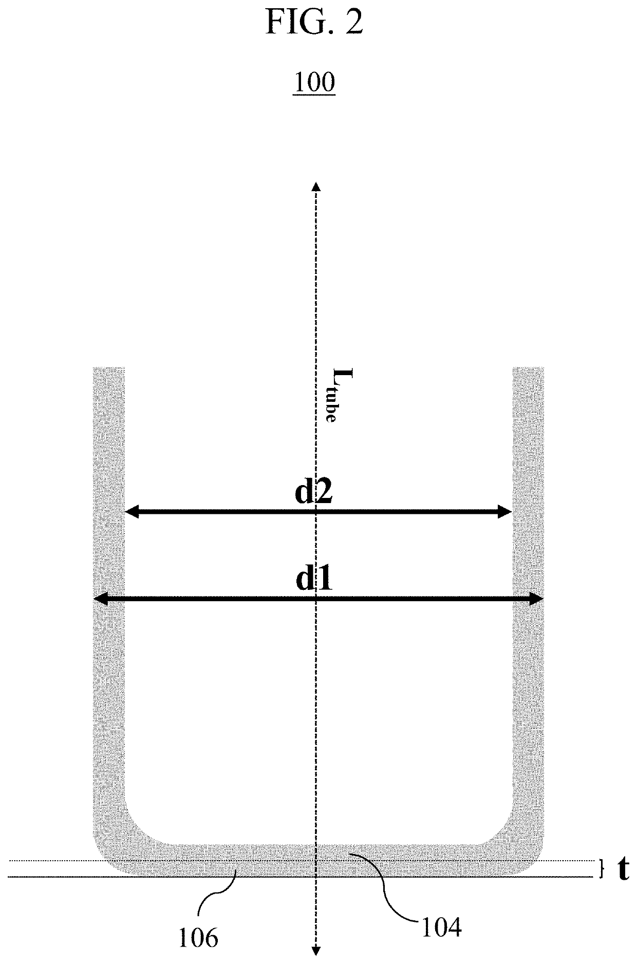
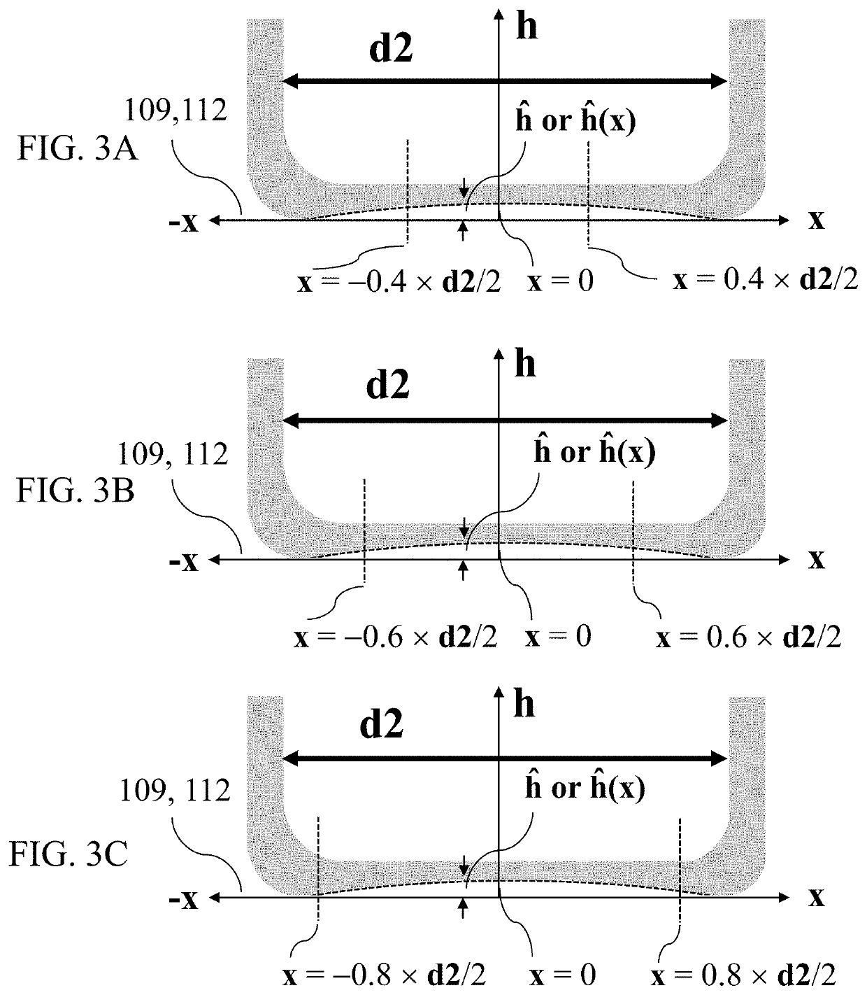
[0125]FIG. 1 shows a cross-sectional view of a glass container according to the invention, wherein for the purpose of an improved illustration the parts of the glass container (i. e. glass tube 101, glass bottom 104 and curved glass heel 107) have been separated from each other. The glass container 100 comprises a glass tube 101 with a first end 102 and a further end 103, the glass tube 101 having an outer diameter d1, an inner diameter d2 and a wall thickness s1. The glass tube 101 is further characterized by a longitudinal axis Ltube that passes through the centre of the first end 102 and the further end 103. The glass tube further comprises a circular glass bottom 104, wherein the circular glass bottom 104 closes the glass tube 101 at the first end 102, wherein the circular glass bottom 104 comprises an inner surface 105 directed to the inside of the glass container 100, an outer surface 106 directed to the outside of the glass container 100 and a centre 110. The glass container ...


PUM

PropertyMeasurementUnit
Lengthaaaaaaaaaa
Fractionaaaaaaaaaa
Lengthaaaaaaaaaa

Abstract

A glass container is provided that includes a tube, a circular bottom, and a longitudinal axis. A curved glass heel extends from an outer end the bottom to the first end of the tube. The two-dimensional distance h(x,y) between a contact plane and the outer surface. The two-dimensional distance is measured in a direction parallel to the axis. The slope magnitude of the outer surface at the given position x,y is given by√{square root over ((dh / dx)2+(dh / dy)2)}.The 75% quantile of values that have been determined for the term√{square root over ((dh / dx)2+(dh / dy)2)}×d1 / h(xy)delta for all given positions x,y within a circular area having a radius of 0.4×d2 / 2 and that correspond to the centre is less than 4100 μm / mm. The adjacent positions x,y increase stepwise by 200 μm, and h(x,y)delta=h(x,y)max−h(x,y)min, h(x,y)max is a maximum value for h(x,y) and h(x,y)min is a minimum value for h(x,y) being determined in that circular area.

Description

CROSS REFERENCE TO RELATED APPLICATIONS[0001]This application claims benefit under 35 USC § 119 of European Application 19219010.6 filed Dec. 20, 2019, the entire contents of which are incorporated herein by reference.BACKGROUND1. Field of the Invention[0002]The present invention relates to a glass container and to a plurality of glass containers, wherein the glass container or each glass container contained in the plurality of glass containers is characterized by an advantageous contour of the outer surface of the circular glass bottom. The present invention also relates to a process for the determination of a physical property of a material that is contained in such a glass container and to the use of a glass container or of a plurality of glass containers for determining a physical property of a material contained in the glass container.2. Description of Related Art[0003]Glass bottles that are used for pharmaceutical purposes (also known as so-called “vials”) are usually prepared...

Claims


Application Information

Patent Timeline
IPC IPC(8): B01L3/00B65D1/02B65D81/30
CPCB01L3/508B65D1/0261B01L2300/0851B01L2300/0832B65D81/30C03B23/099A61J1/065A61J1/1468C03B23/043C03B23/057C03B23/047B01L2300/0835B01L2200/12C03B23/045C03B21/06C03B23/08C03B23/09C03B23/112A61J1/05
Inventor FROST, ROBERTMOSELER, DORISWEIDMANN, GÜNTERHUHN, ROMANTHOMAS, JENS ULRICHHUMBERTJEAN, ALEXANDERLENTES, FRANK-THOMASLANGSDORF, ANDREAS
Owner SCHOTT PHARMA AG & CO KGAA
Learn More