
Anti-rocket system

a rocket system and anti-missile technology, applied in direction controllers, instruments, using reradiation, etc., can solve the problems of serious threat to the morale of the population, damage to property and humans, and damage to the ground to ground rocket such as the grad

Active Publication Date: 2015-05-28
ISRAEL AEROSPACE IND
View PDF12 Cites 19 Cited by
  • Summary
  • Abstract
  • Description
  • Claims
  • Application Information

AI Technical Summary

Benefits of technology

The present patent describes a counter-flying object system that includes a sensor array and a control system. The sensor array includes at least one active sensor and two passive sensors. The control system uses the sensor array to determine the location of the flying object and the interceptor missile. The system generates a mission data that includes information about the predicted interception point, the time of launch, and the separation time of the interceptor missile. The interceptor missile is designed to selectively use the mission data, the uplink messages, and the navigation data to guide it towards the predicted interception point and activate the warhead if lethality criteria are met. The system can be used against various threats such as ground to ground rockets, aircraft, and cruise missiles. The interceptor missile includes a separable motor, a warhead, and a navigation system that includes an airborne computer and body angles measurement unit. The system can also track the interceptor missile for accurate guidance.

Problems solved by technology

Ground to Ground (GTG) rockets such as the GRAD are a serious threat when hitting a territory populated by civilians.
However, the simple GTG rocket structure has a clear inherent advantage of a very simple launching means and a low-cost price tag, facilitating deployment of numerous launchers and utilization of numerous rockets which can be launched in large numbers over a long period of time towards friendly territory, which may cause not only damage to property and humans, but also substantial damage to the morale of the population which is subjected to prolonged and continuous threats.
The combined effect of kinetic energy accumulated by the impinging rocket and the detonated explosive of war-head fragments are sufficient in many cases to penetrate walls and cause significant damage to buildings.
Whilst thick concrete and other structures may block penetration of the rocket, it is practically infeasible to shield buildings with armored concrete, when considering for example several cities that are in the range of a GRAD threat.
Another significant challenge of the GTG rockets' interception relates to the lethality problem: the vulnerable area of the rocket has relatively small dimensions and is surrounded by one or two layers of steel-made balls fitted into the warhead explosive.
So to summarize, the main challenges of GTG rocket interception are related to a very tight time budget and to a very small vulnerable area of the target's warhead.
The net effect of the specified characteristics imposes utilization of a sophisticated and costly defense system compared to a very simple and low-cost rocket launch system.
The latter are not only susceptible to hits but also involve significant costs per each intercept, compared to the negligible costs of each launched rocket.

Method used


Image

  • Anti-rocket system
  • Anti-rocket system
  • Anti-rocket system

Examples


Embodiment Construction

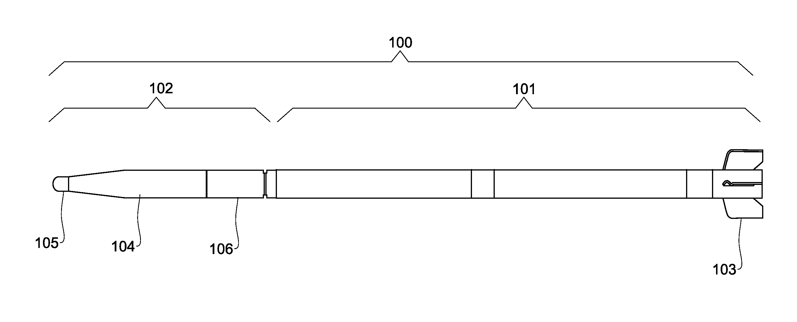
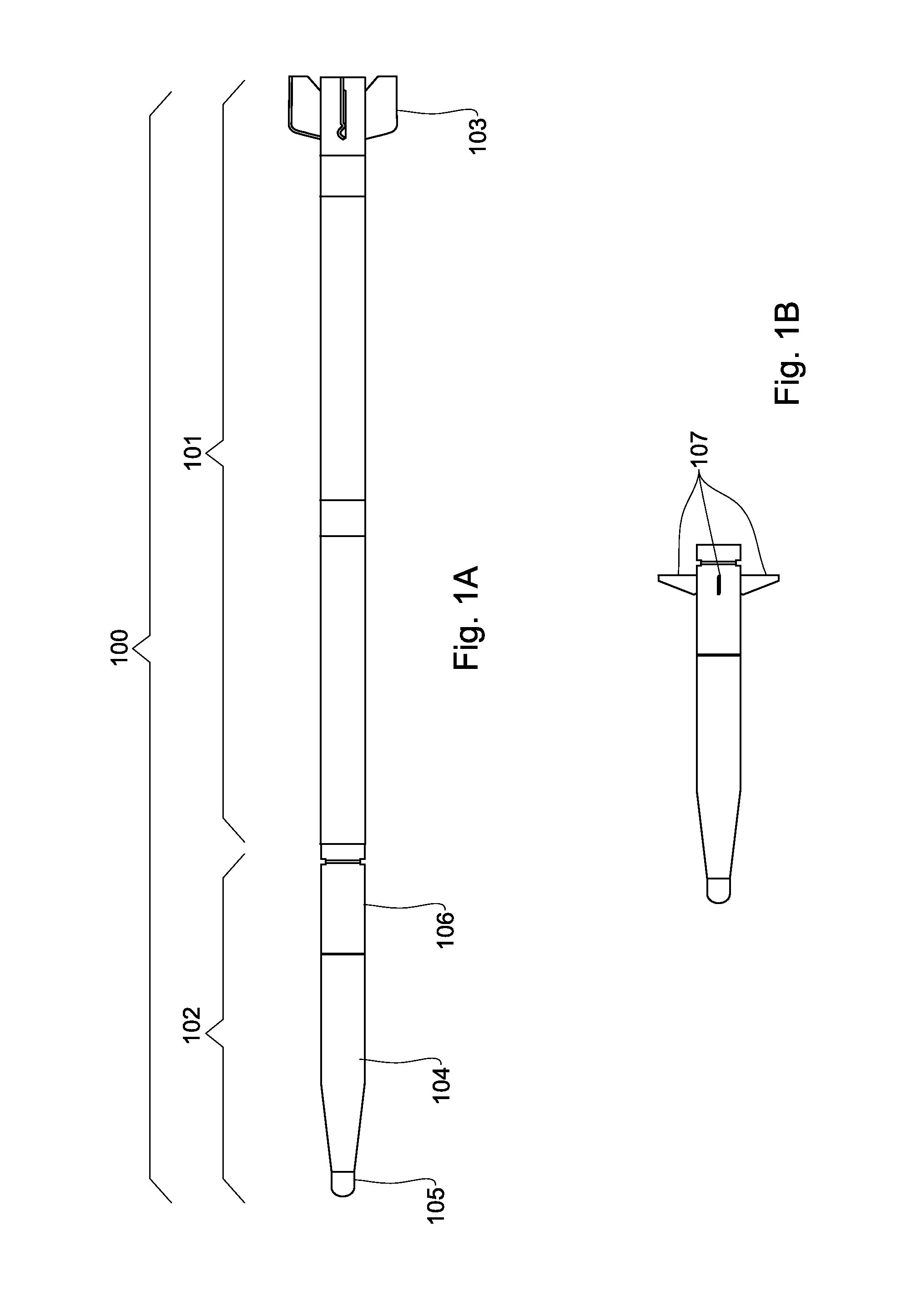
[0113]Attention is first drawn to FIG. 1A, showing a schematic illustration of an intercept missile, in accordance with certain embodiments of the invention. Thus, an interception missile 100 includes a solid motor 101 called also engine section, and a main section 102 which is seeker-less. The engine section further includes (e.g. wrap around) fins 103 which constitute an integral part of the solid motor and serve for stabilizing the missile during the boost and coast phases of the flight until separation occurs. The main section 102 consists of warhead 104 including its associated proximity fuse 105 and electronic section 106.

[0114]Note that in accordance with certain embodiments, the engine section is in fact an engine of a rocket (e.g. GRAD, MLRS etc.). The engine serves two main purposes: for boosting the interceptor until sufficient energy is accumulated and for increasing of the interceptor's ballistic coefficient during the coasting phase, whereupon a separation stage occurs...


PUM


Abstract

A counter-flying object system comprising a sensor array including at least one active sensor configured to detect and track the flying object, and a missile launcher configured to launch an interceptor to intercept the flying object, wherein upon launching of the interceptor, the sensor array is configured to determine the location of the interceptor and send said object and interceptor locations to a control system, the control system being configured to provide mission data to the interceptor based on said object and interceptor locations for guiding the interceptor toward the flying object and activating a fragmentation warhead on or in the vicinity of said flying object when a lethality criteria is met.

Description

FIELD OF THE INVENTION[0001]This invention relates to the field of anti-missile missiles (AMMs).BACKGROUND OF THE INVENTION[0002]Ground to Ground (GTG) rockets such as the GRAD are a serious threat when hitting a territory populated by civilians. Such rockets are of relatively simple structure as they do not employ a guidance system and are devoid of an on-board controllable steering mechanism. The hitting point at the target territory is generally dependent on the distance from the launcher, the launcher's angular positioning (azimuth and inclination) and rocket's kinematics and ballistic characteristics. A variety of certain unpredictable factors may influence the accuracy of the hitting point: winds profile during the rocket flight, asymmetry of nozzle erosion during the boost phase, and missile asymmetry (geometry and center of gravity position) due to manufacturing deviations. Shortening of the boost phase and spinning of the rocket are common use techniques for improvement of ...

Claims


Application Information

Patent Timeline
IPC IPC(8): F41H11/02
CPCF41H11/02F41G7/30G01S7/003G01S13/003G01S13/878F42B15/01F41G7/303
Inventor ROVINSKY, JACOB
Owner ISRAEL AEROSPACE IND
Learn More