
Radiation imaging sensor

a technology of imaging sensor and infrared sensor, which is applied in the field of radiation imaging sensor, can solve the problems of large space occupation, high cost, and sometimes relatively slow imaging process, and achieve the effects of faster imaging process, compact construction, and high spatial resolution

Active Publication Date: 2015-05-28
FRAUNHOFER GESELLSCHAFT ZUR FOERDERUNG DER ANGEWANDTEN FORSCHUNG EV
View PDF1 Cites 2 Cited by
  • Summary
  • Abstract
  • Description
  • Claims
  • Application Information

AI Technical Summary

Benefits of technology

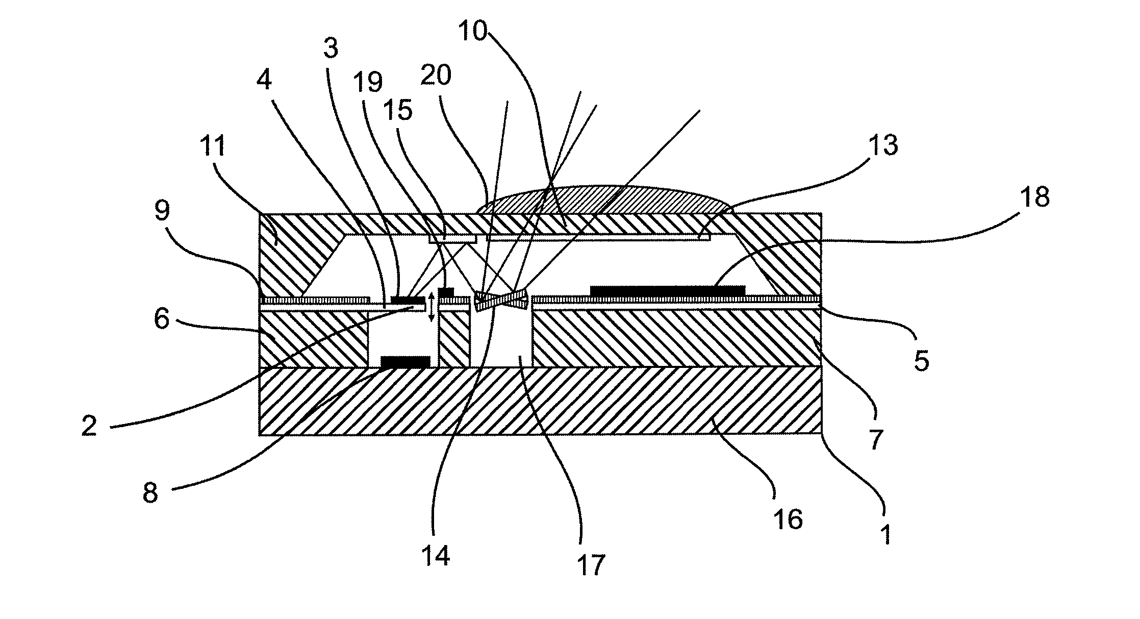
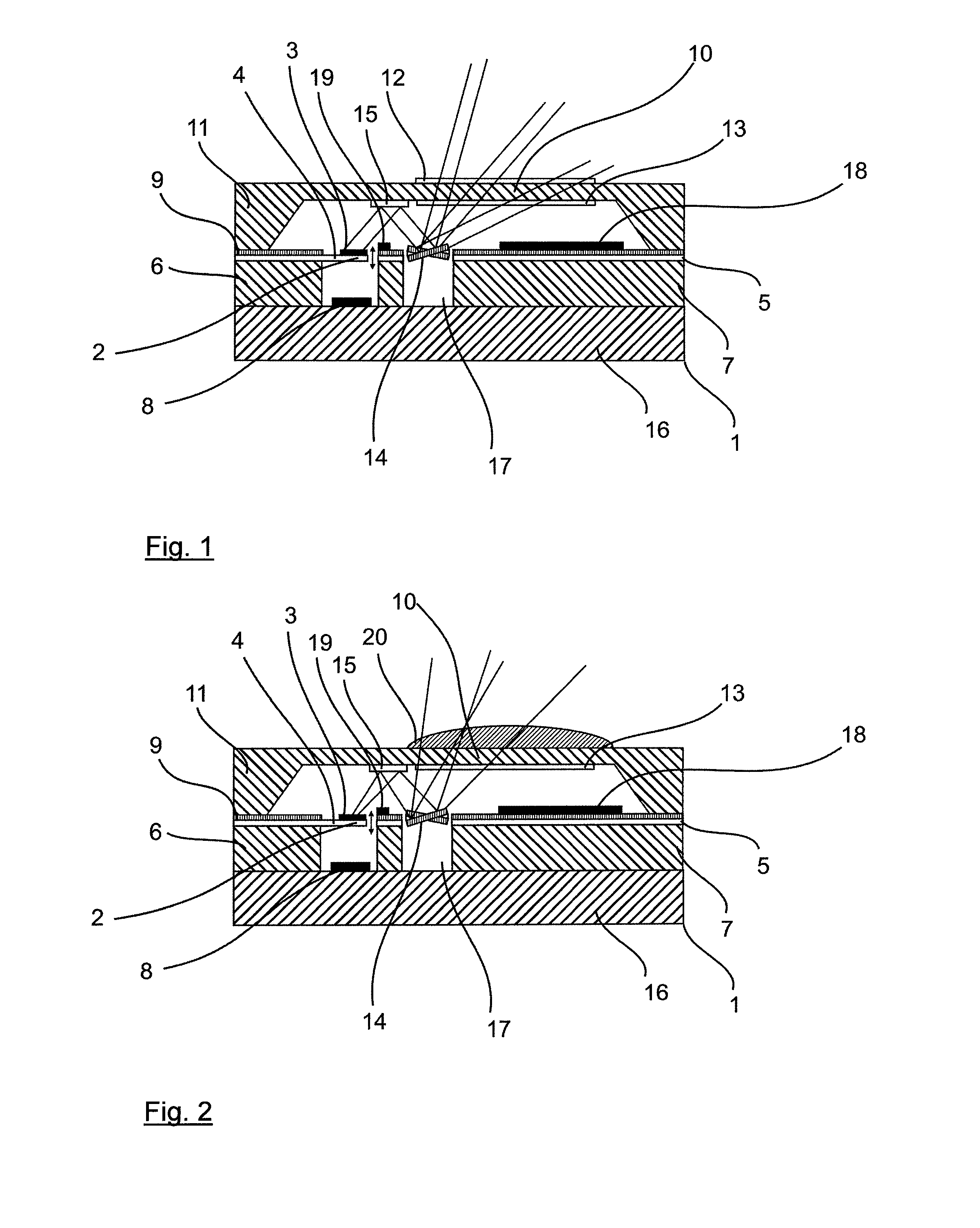
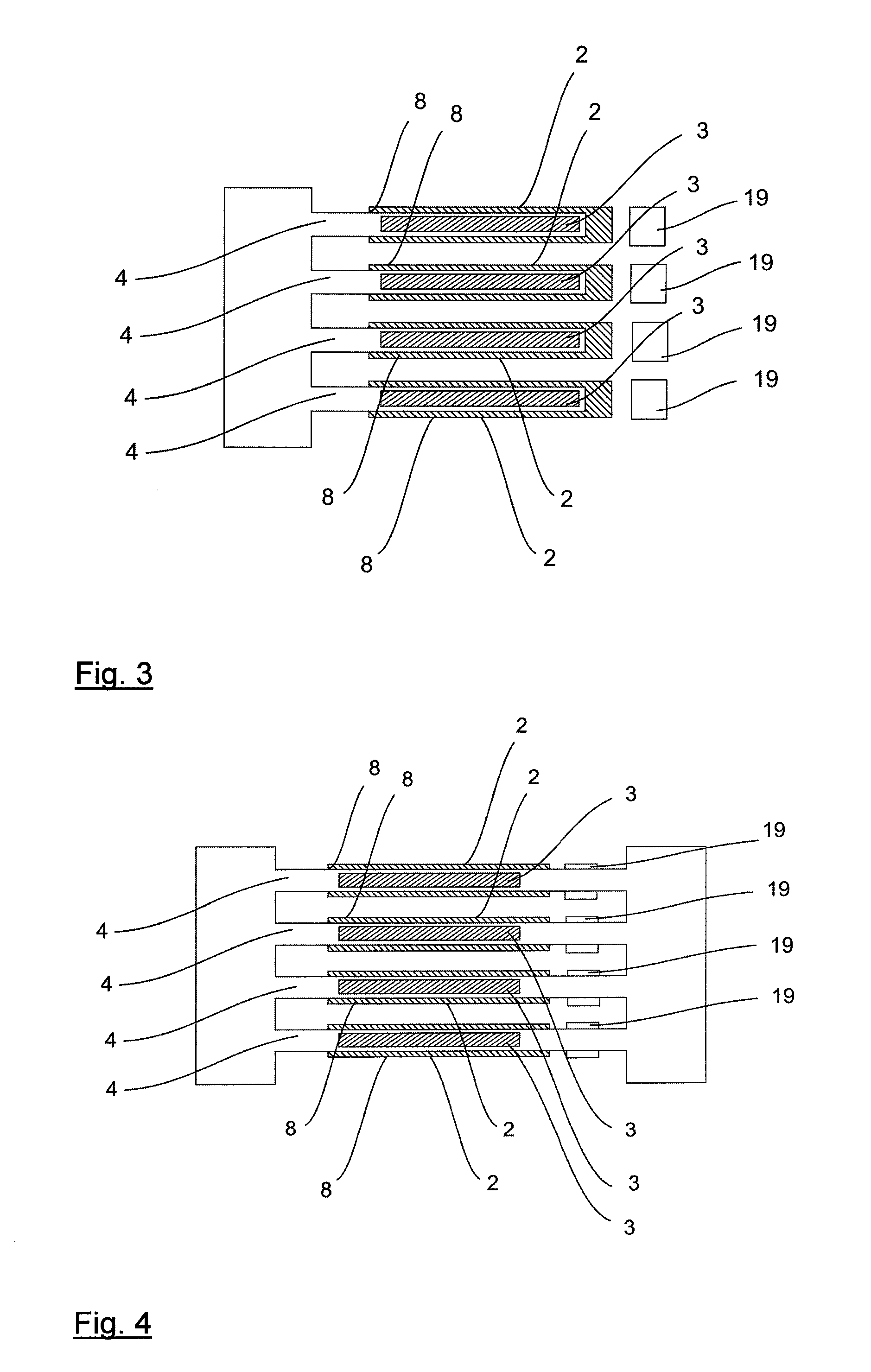
The proposed radiation sensor uses a scanning element and / or a scanning device to scan a region to be imaged with the sensor in at least one axis. This means that the size of the sensor is reduced compared to an array-like arrangement of several detection elements. The detection element is a micromechanical resonator that absorbs radiation and reacts with high sensitivity to extremely small variations of the intensity of the incident radiation with a slight shift in its resonance frequency. The resonance frequency is used as a measure of the intensity of the incident radiation to be detected. The scanning device and the detection element can be advantageously realized in the most compact manner, and can preferably be integrated into a single substrate as a monolithic structure. The sensor has high sensitivity and can react quickly to changes in radiation. A plurality of detection elements can be used in a matrix-like or array-like arrangement to achieve higher spatial resolution or faster imaging process. The sensor has a compact construction and can be easily excited and detected. The detection elements should be separated from one another only by a narrow gap and can be accommodated in separate vacuum cavities for different applications.

Problems solved by technology

Imaging infrared sensor arrays require a large amount of space however, are very expensive and can sometimes be relatively slow.

Method used


Image

  • Radiation imaging sensor
  • Radiation imaging sensor
  • Radiation imaging sensor

Examples


Embodiment Construction

[0007]The object is achieved with the radiation imaging sensor in accordance with claim 1. Advantageous configurations of the radiation sensor are the subject matter of the dependent claims or can be inferred from the following description together with the exemplary embodiments.

[0008]The proposed radiation imaging sensor comprises at least one detection element which is implemented on a substrate as a micromechanical resonator and absorbs the radiation to be detected, at least one excitation device, with which the detection element can be set into resonant oscillation, and at least one detection device with which a shift in the resonance frequency of the detection element under exposure to radiation can be detected. The proposed radiation sensor is characterized by the fact that it comprises a scanning device with a single-axis or multi-axis tiltable scanning element. The ability to tilt the device means that the detection element can be used to detect radiation from different dire...


PUM


Abstract

The present invention relates to a radiation imaging sensor with at least one detection element, which is implemented on a substrate as a micromechanical resonator and which absorbs the radiation to be detected. The resonator is set into a resonant oscillation with an excitation device and a shift in the resonance frequency of the detection element under exposure to radiation is detected with a detection device. The radiation sensor is characterized by the fact that it comprises a scanning device with a single-axis or multi-axis tiltable scanning element. The facility to tilt the device means that the detection element can be used to detect radiation from different directions. The imaging sensor can be realized in a compact manner and be economically produced.

Description

TECHNICAL FIELD OF APPLICATION[0001]The present invention relates to a radiation imaging sensor with at least one detection element which is implemented on a substrate as a micromechanical resonator and absorbs radiation to be detected, and with an excitation device, with which the detection element can be set into resonant oscillation, and a detection device with which a shift in the resonance frequency of the detection element under exposure to radiation can be detected.[0002]Such a radiation sensor works according to the bolometer principle. Bolometers detect electromagnetic radiation by absorbing the radiation, converting it into heat and quantitatively evaluating this quantity of heat. Bolometers are used, inter alia, in thermographic cameras. As well as two-dimensional matrix systems, one-dimensional arrays and discrete single detectors also exist.PRIOR ART[0003]Known infrared radiation sensors working according to the Bolometer principle typically comprise a structured diaphr...

Claims


Application Information

Patent Timeline
IPC IPC(8): G01J5/10G01J5/08G01J5/02
CPCG01J5/10G01J5/022G01J5/0806G01J5/0205G01J5/0871G01J5/44G01J2005/0077G01J5/047G01J5/045G01J5/084G01J5/0837
Inventor HOFMANN, ULRICHWEISS, MANFREDJANES, JOACHIMSENGER, FRANK
Owner FRAUNHOFER GESELLSCHAFT ZUR FOERDERUNG DER ANGEWANDTEN FORSCHUNG EV
Learn More