Railway installation synchronization monitoring system

a technology of installation synchronization and monitoring system, which is applied in the direction of television system, railway signalling, transportation and packaging, etc., can solve the problems of difficult comparison and analysis of data with respect to a baseline, difficult to thoroughly monitor railroads and streetcar lines, and cracks in deteriorating tunnels. achieve the effect of improving the efficiency of installation management, and ensuring the accuracy of data

Inactive Publication Date: 2015-05-28
SMARTECH
View PDF3 Cites 14 Cited by
  • Summary
  • Abstract
  • Description
  • Claims
  • Application Information

AI Technical Summary

Benefits of technology

[0020]According to exemplary embodiments of the present invention, a position checking unit may measure an exact position of a track, a streetcar line, sleepers and/or a tunnel installation. Thus, the precision and reliability of data obtained using a railway installation monitoring system according to the exemplary embodiments of present invention may be much higher than in the related art.
[0021]In particular, the precision of data can be greatly increased since a distance error hardly occurs even with respect to a track or a streetcar line.
[0022]Also, according to exemplary embodiments of the present invention, since data can be accumulatively stored at a uniform measurement position, effective comparison data can

Problems solved by technology

However, it's challenging to thoroughly monitor railroads and streetcar lines for safety-assurance purposes since a moving distance is long and monitoring should be performed within a short period during which trains do not move.
However, it is not easy to detect cracks occurring in a deteriorating tunnel.
Also, although data regarding a major position is measured and obtained, the data is difficult to compare and analyze with respect to a baseline when the data is not synchronized with a measurement position.
That is, a fine change in a rail may be detected when data obtained at the same measurement position is continuously compared with the baseline, but is difficult to detect when data obtained at a non-fixed measurement position is compared with the baseline.
However, inconvenience may be caused to a user when the current method of the related art (e.g., a method of accumulatively estimating a distance based on a rotational speed of a wheel, a method of estimating a distance by perfor

Method used


Image

  • Railway installation synchronization monitoring system
  • Railway installation synchronization monitoring system
  • Railway installation synchronization monitoring system

Examples


Embodiment Construction

[0030]The invention is described more fully hereinafter with reference to the accompanying drawings, in which embodiments of the invention are shown. This invention may, however, be embodied in many different forms and should not be construed as limited to the embodiments set forth herein. Rather, these embodiments are provided so that this disclosure is thorough, and will fully convey the scope of the invention to those skilled in the art. In the drawings, the size and relative sizes of layers and regions may be exaggerated for clarity. Like reference numerals in the drawings denote like elements.

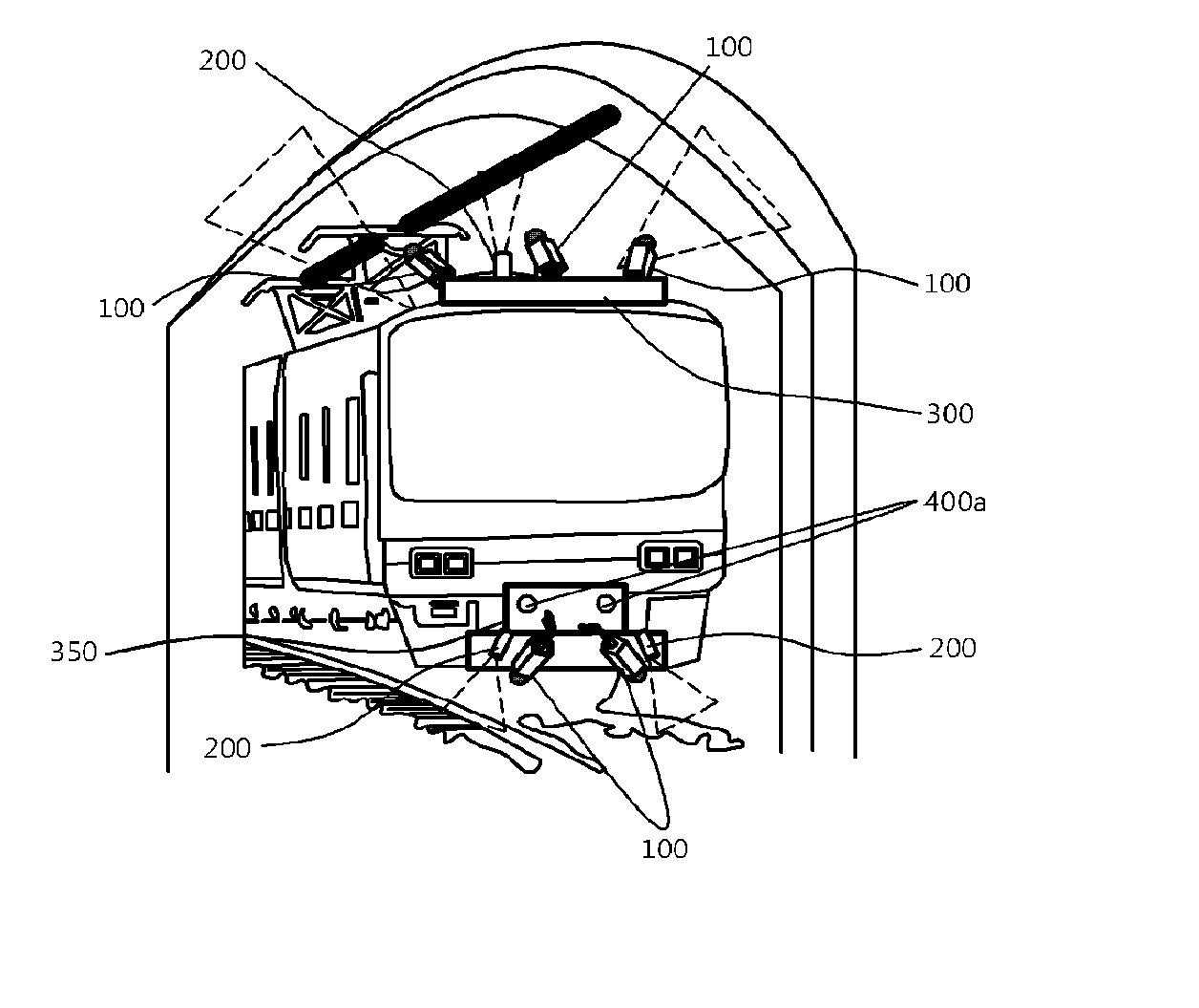
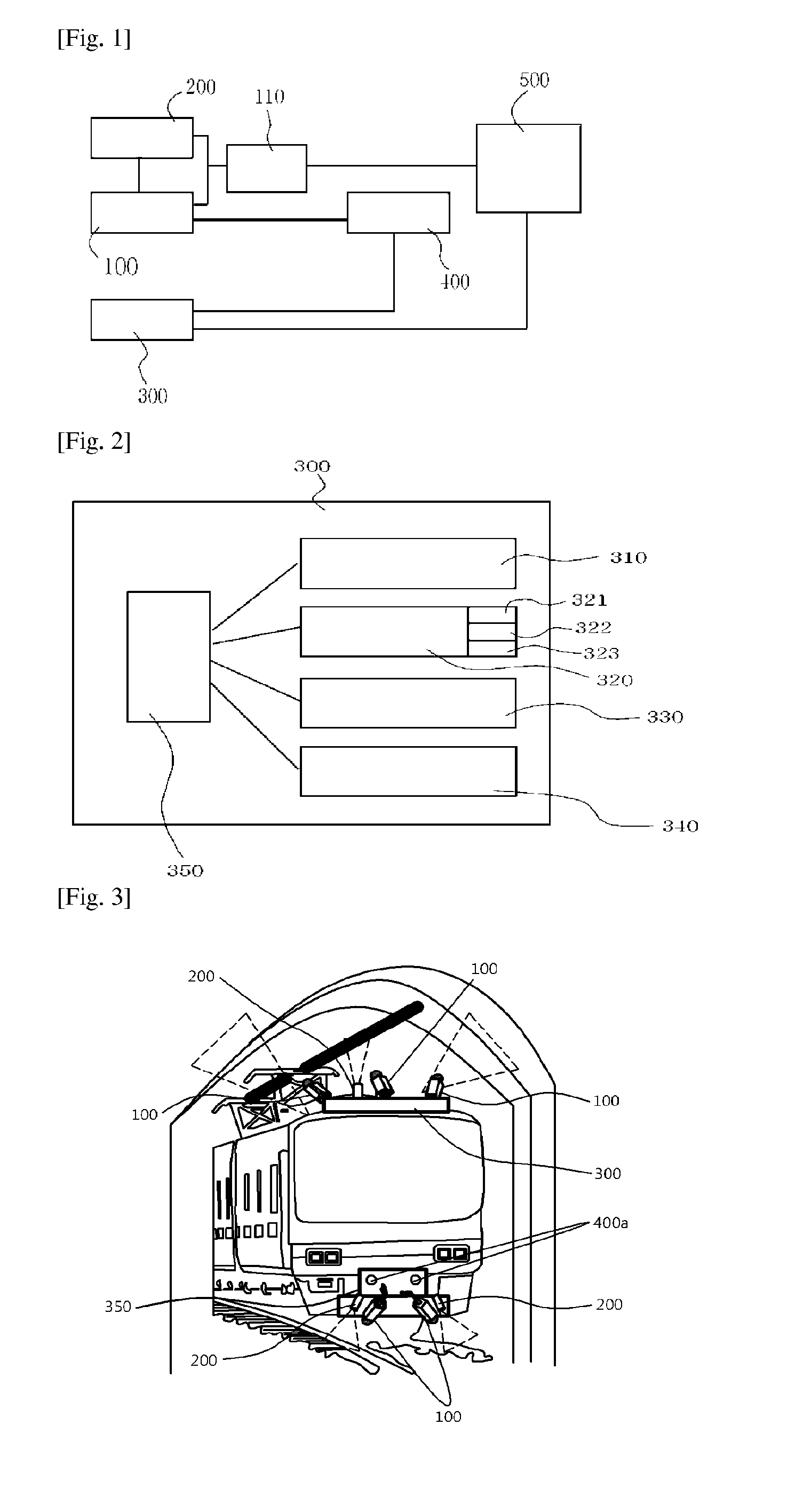
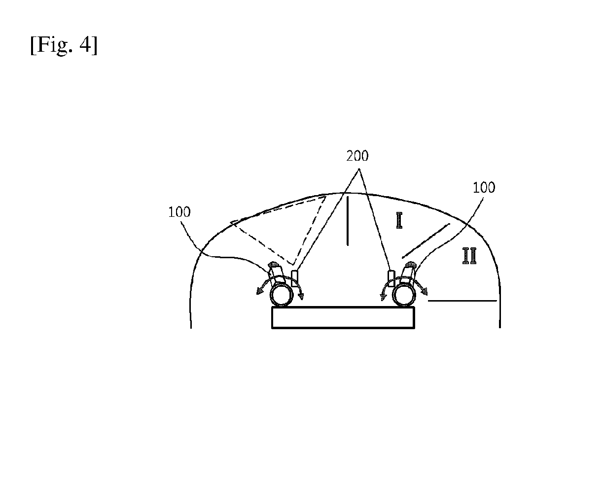
[0031]Exemplary embodiments of the present invention provide a railway installation monitoring system including a laser generator 200 installed on a train, a camera 100 operated while being interlinked with the laser generator 200 and configured to obtain image information data to monitor and measure major railway installations, a three-dimensional (3D) image information conversion device ...


PUM


Abstract

A railway installation monitoring system may include: a laser generator that is provided on a train; a camera that is operated in connection with the laser generator so as to be capable of monitoring a railway installation and of acquiring image information data that is measured; a three-dimensional image information conversion device that uses the image information data acquired by the laser generator and the camera and converts the data into three-dimensional image information; a position determination unit that determines the position of the railway installation to be measured; a signal processing device that sends an operating command for the laser generator or/and the camera; and an overall data processing device that processes, analyzes, interprets, or stores the image information data, the three-dimensional image information, or the data transmitted from the position determination unit.

Description

CROSS-REFERENCE TO RELATED APPLICATIONS[0001]This application is the National Stage of International Application PCT / KR2013 / 005797, filed on Jul. 1, 2013, and claims priority from and the benefit of Korean Patent application No. 10-2012-0072089, filed on Jul. 3, 2012, which are incorporated by reference for all purposes as if fully set forth herein.BACKGROUND[0002]1. Field[0003]Exemplary embodiments of the present invention relate, in general, to a system for monitoring a railway by synchronizing dynamic characteristics of a train moving along tracks and data for monitoring railway installations with a predetermined moving distance and, more particularly, to a system for monitoring a railway installation while repeatedly accumulating and processing data obtained by measuring a rail, a streetcar line, or a tunnel structure using a monitoring apparatus including a laser generator installed on a train, a camera for obtaining three-dimensional (3D) coordinates, and a measuring device th...

Claims


Application Information

Patent Timeline
IPC IPC(8): B61F9/00B61L3/00H04N13/00H04N7/18H04N13/02
CPCB61F9/005H04N7/181B61L3/002H04N13/0007H04N13/0203B61L23/042B61L23/06B61L25/06H04N13/106H04N13/204
Inventor JEONG, SOONBAEKIM, TAEJINKIM, GI-DONKIM, HYOUNWOO
Owner SMARTECH
Why Eureka
Try Eureka