
Cable-Based Sensor for Detecting Material Level and Temperature

Active Publication Date: 2015-05-28
FINETEK CO LTD
View PDF8 Cites 5 Cited by
  • Summary
  • Abstract
  • Description
  • Claims
  • Application Information

AI Technical Summary

Benefits of technology

The present invention is a cable-based sensor that can detect the level and temperature of liquids and solids. It has a cable that is firmly connected to an electronic box to protect it from impact by solid materials. This technology can be used to accurately measure the levels and temperatures of materials in a variety of applications.

Problems solved by technology

In some particular industries, when the temperature of the material stored in the silo is not properly controlled, a dry and dusty material may cause a dust explosion.
However, the foregoing conventional sensors cannot detect solid material because detecting cables of the conventional sensors are easily damaged by impacts of the solid material.

Method used


Image

  • Cable-Based Sensor for Detecting Material Level and Temperature
  • Cable-Based Sensor for Detecting Material Level and Temperature
  • Cable-Based Sensor for Detecting Material Level and Temperature

Examples


first embodiment

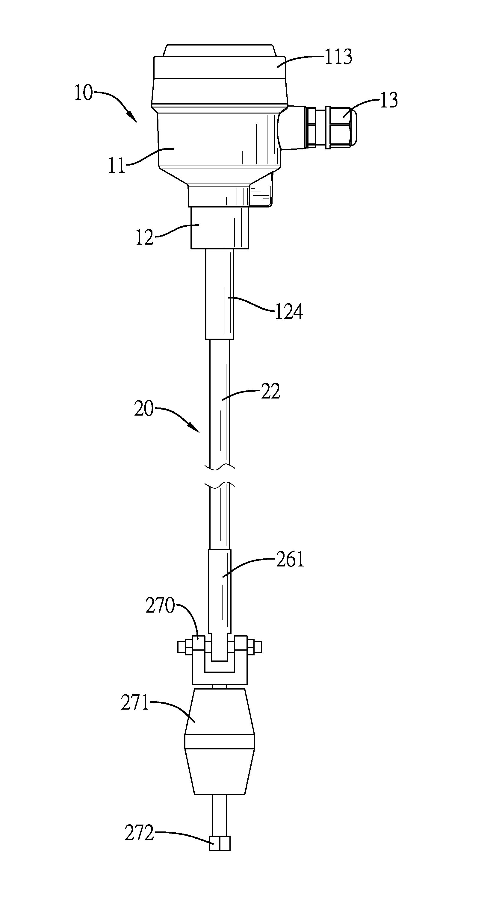
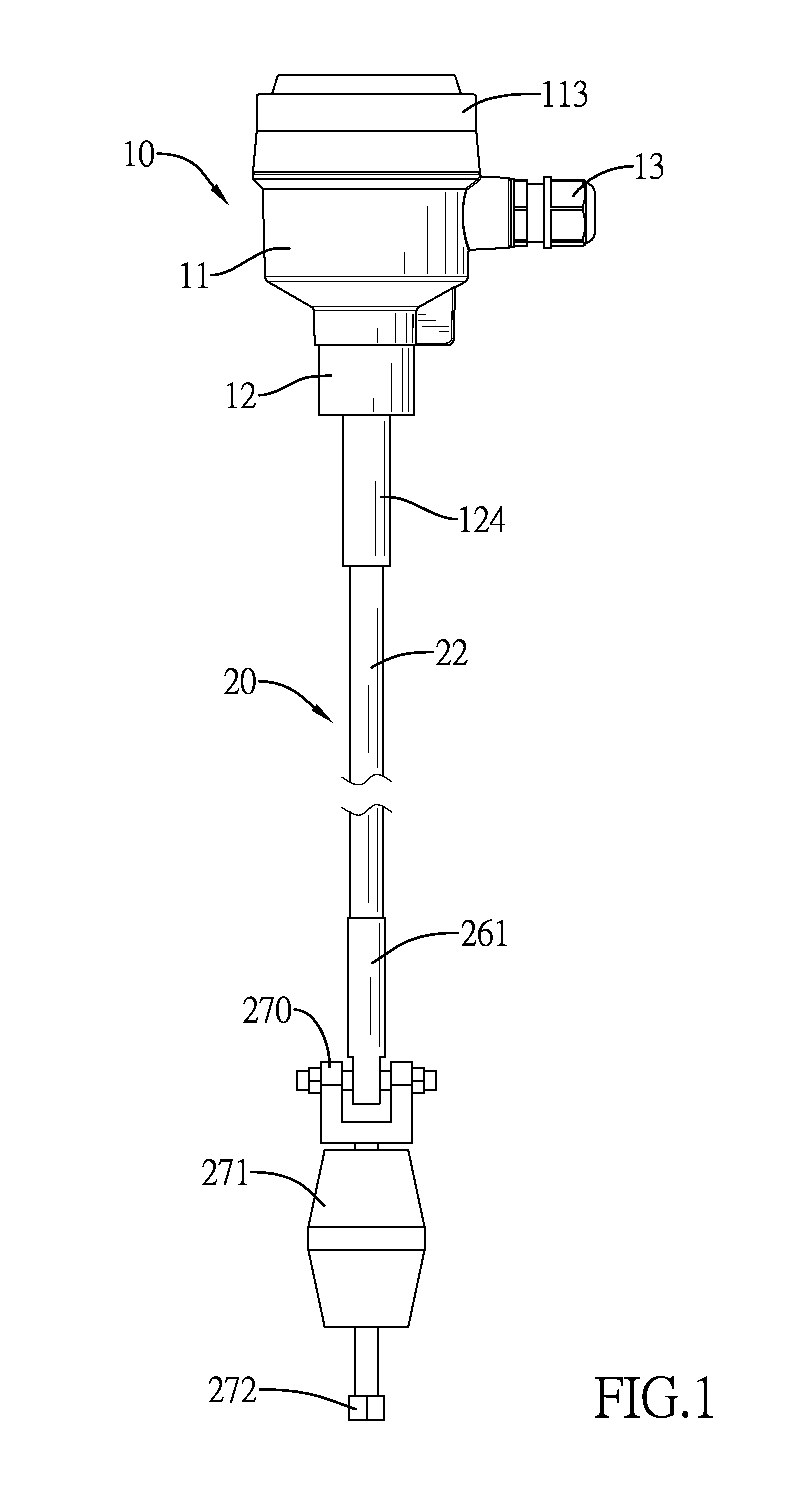
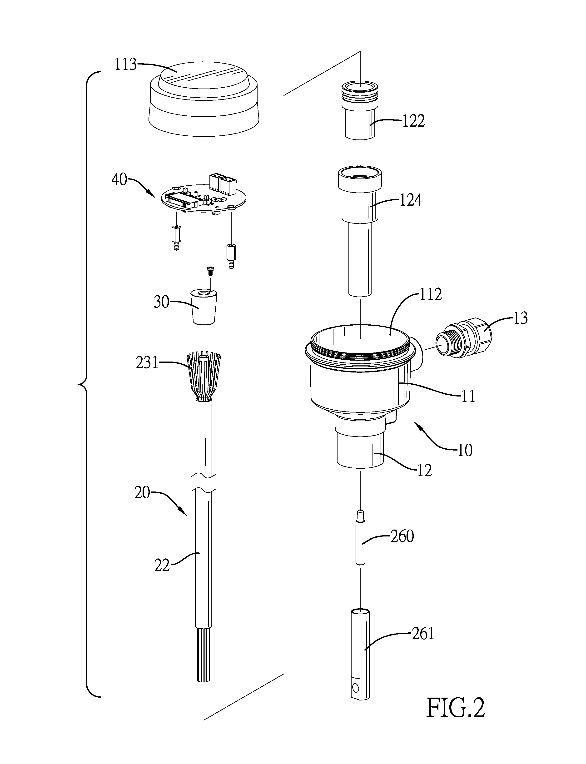
[0036]With reference to FIGS. 1, 2 and 3, a cable-based sensor of the present invention comprises an electronic box 10, a cable 20, a stopper 30, and a signal processing module 40.

[0037]The electronic box 10 includes a top 11, a bottom 12, a space 111 formed in the top 11, a hole 121 and a base 122. The hole 121 is formed through the bottom 12 and communicates with the space 111. The base 122 is mounted in the bottom 12. A tapered hole 123 is formed through the base 122.

[0038]The cable 20 includes a sensing channel 21, an insulation layer 22 for covering the sensing channel 21, a plurality of steel wires 23 and temperature sensing units 24. A first end of the cable 20 extends to the tapered hole 123 of the base 122 and the hole 121 of the electronic box 10. The steel wires 23 are mounted around the sensing channel 21 and embedded in the insulation layer 22. Terminals of the steel wires 23 extend out of the insulation layer 22 and spread to form a cable bud 231. The cable bud 231 is ...

second embodiment

[0052]the installing base 50 is shown in FIG. 15, and the baseboard 51 is mounted on the inclined roof. An arc notch 511 is formed in the installing top of the baseboard 51. Two arc ribs 522 separately extend from two opposite sides of the rotating base 52, and two sliding rails 523 are separately formed through the two arc ribs 522. Two mounting units 524 separately extend through the sliding rails 523, and are mounted in the arc notch 511. The cable 20 extends through the rotating base 52, the arc notch 511, and the baseboard 51. The rotating base 52 can be rotated in the arc notch 511, and a rotation angle of the rotating base 52 can be limited by the sliding rails 523 for avoiding over rotating.

third embodiment

[0053]the installing base 50 is shown in FIG. 16. The installing base 50 comprises a turning base 53, a turning ball 54, and a substrate 55. The turning ball 54 is positioned between the turning base 53 and the substrate 55, and the cable 20 extends through the turning base 53, the turning ball 54 and the substrate 55. The bottom 12 of the electronic box 10 is further mounted on the turning ball 54, and the turning ball 54 can be turned to any direction for adjusting the cable 20 to be vertical with the horizon.

[0054]In short, the cable 20 is connected to the electronic box 10 by enforcing the cable bud 231 to be sandwiched between the stopper 30 and the base 122. A structure of the cable bud 231 can strengthen a connection between the cable 20 and the electronic box 10 for avoiding damages caused by impacts of solid materials. Therefore, the cable 20 can be firmly mounted on the bottom 12 of the electronic box 10.

[0055]The cable 20 includes the temperature sensing units 24 and the ...


PUM


Abstract

A cable-base sensor can detect a material level and temperatures of a material stored in a silo. The cable-base sensor comprises an electronic box, a cable, a stopper, and a signal processing module. The electronic box comprises a base and a space for containing the signal processing module, and a hole is formed through a bottom of the electronic box. The base is mounted in the bottom, and a tapered hole is formed through the base. A first end of the cable extents into the tapered hole and the hole, and spreads to form a cable bud. The stopper is a tapered block and pressed into the tapered hole for enforcing the cable bud to be sandwiched between the stopper and the base. The cable bud strengthens a connection between the electronic box and the cable for preventing damages from solid materials.

Description

BACKGROUND OF THE INVENTION[0001]1. Field of the Invention[0002]The present invention relates to a cable-based sensor, particularly to a cable-based sensor for detecting material level and temperature.[0003]2. Description of the Related Art[0004]For management of bulk material stored in a silo, a sensor for detecting material level is very important. The material level means a height of the material in the silo, and the material level can be converted to obtain the amount of the material stored in the silo. The sensor can be applied to petrochemical industry, food industry, feed industry, steel industry, cement industry, etc. Materials stored in a silo may be solid, liquid, or liquid-solid mixture. For example, the materials may be petroleum, coal, iron sand, cement, flour, cattle fat, etc. When each material is stored in a silo, temperature, moisture and an amount of the material will influence the quality of the materials. In some particular industries, when the temperature of the...

Claims


Application Information

Patent Timeline
IPC IPC(8): G01K1/08G01F23/00G01K13/10G01K1/14
CPCG01K1/08G01F23/0061G01K13/10G01K1/026G01F23/246G01F23/804
Inventor HUANG, CHIEN-LUNGCHEN, SHENG-SHOUTSAI, TZU-CHUANYU, YAO-CHENCHENG, CHAO-KAIWU, TING-KUO
Owner FINETEK CO LTD
Learn More