Elevator system and method for implementing a sound system for an elevator

Active Publication Date: 2015-05-28
KONE CORP
View PDF3 Cites 3 Cited by
  • Summary
  • Abstract
  • Description
  • Claims
  • Application Information

AI Technical Summary

Problems solved by technology

The sound produced by an elevator sound system can, of course, be considered a source of noise in certain operating situations.
Noise disturbs in particular the hearing impaired and people with poor hearing.
As background noise increases, identifying the direction of a sound becomes difficult.
If an elevator group comprises more than

Method used


Image

  • Elevator system and method for implementing a sound system for an elevator
  • Elevator system and method for implementing a sound system for an elevator
  • Elevator system and method for implementing a sound system for an elevator

Examples


Embodiment Construction

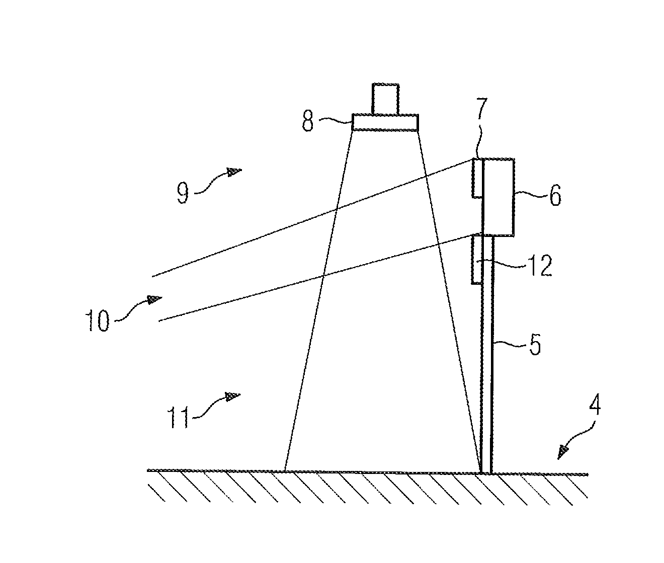
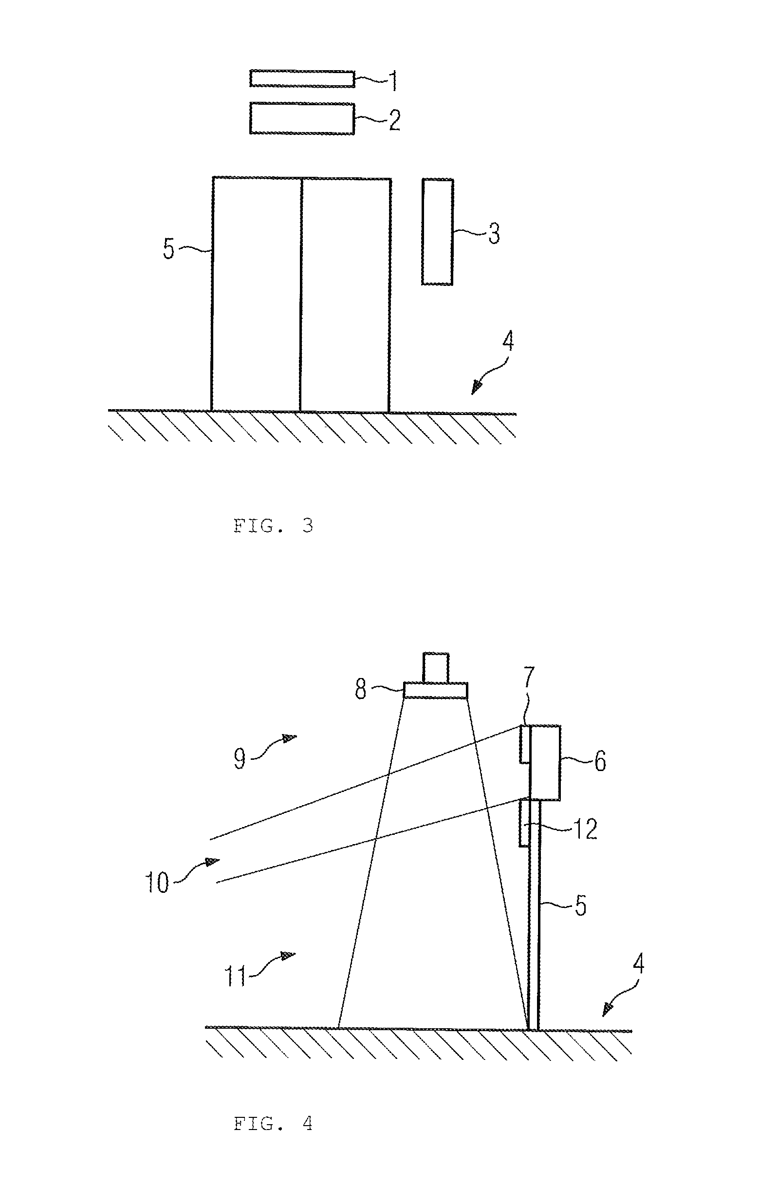
[0029]Known from Panphonics Oy's international patent publication WO 2009 / 127787 is a plate-like electrostatic actuator producing a directed sound field. The plate-like electrostatic actuator producing a directed sound field presented in our present application can be more particularly the actuator described in the aforementioned patent application publication or an actuator of similar type, more particularly we use the “Sound Shower” arrangement as defined in Panphonics Oy's “Company and technology presentation” (August 2011).

[0030]The directivity of the sound field in the actuator described in patent application publication WO 2009 / 127787 is based on a delay directing a sound field being formed with an RC circuit, which is at least partly composed of components of the electrostatic actuator. The electrostatic actuator itself functions as the capacitor of the RC circuit, because the stators are so close to each other that the capacitance of the electrostatic actuator forms to be qu...


PUM


Abstract

Improvement to a sound system for an elevator system and method for implementing the sound system for an elevator. The elevator sound system is improved by replacing at least one loudspeaker to be used in the sound system with a plate-like electrostatic actuator producing a directed sound field. The patent application also contains an independent claim for a method for implementing a sound system for an elevator.

Description

[0001]This application is a continuation of PCT International Application No. PCT / FI2013 / 050800 which has an International filing date of Aug. 15, 2013, and which claims priority to Finnish patent application No. 20125857 filed Aug. 17, 2012, the entire contents of both which are incorporated herein by reference.FIELD OF THE INVENTION[0002]The invention relates to the field of elevator technology and more particularly to the implementation of sound systems to be used in elevators.STATE OF THE ART[0003]An elevator gong is a sound-producing device to be used in elevator systems, which device announces the arrival and / or direction of an elevator, typically with a typical ping-type sound. An elevator gong is typically disposed in front of the elevator above the door opening.[0004]A lift announcer (ACU) is a sound-producing device to be used in elevator systems, which is used in the lobbies of buildings in the elevator waiting areas but also in the elevators themselves, on the one hand t...

Claims


Application Information

Patent Timeline
IPC IPC(8): H04R19/00
CPCH04R19/00B66B3/00B66B3/006H04R1/028H04R1/023H04R19/02H04R27/02H04R2201/021
Inventor PAHKALA, KARIKUJALA, MATTI
Owner KONE CORP
Why Eureka
Try Eureka