
Jig for guide pin piercing

a piercing jig and guide pin technology, applied in the field of jigs, can solve the problems of the device of patent document 1 having another problem, the inability to determine the proper position and angle of the second bone tunnel to be bored through the shinbone top portion, etc., and achieve the effect of reducing the number of components, easy transportation, and easy assembly

Active Publication Date: 2015-06-04
TEIJIN MEDICAL TECH CO LTD +1
View PDF3 Cites 12 Cited by
  • Summary
  • Abstract
  • Description
  • Claims
  • Application Information

AI Technical Summary

Benefits of technology

[0009]The present invention has been made in the above circumstances, and an object of the present invention is therefore to provide a guide pin piercing jig which make it possible to pierce a living body bone with plural parallel guide pins for hollow drills to a proper portion in a proper direction even if no reference bone tunnel is bored, to thereby make it possible to bore plural bone tunnels through the living body bone by the hollow drills that are guided by the respective guide pins inserted therein and to form a bone tunnel that has a rectangular or elliptical opening and hence is suitable for tendon transplantation by boring a link tunnel that connects the plural bone tunnels and subjecting it to chiseling or the like.
[0023]As described above, the guide pin piercing jig according to invention makes it possible to pierce a living body bone with plural guide pins to a proper portion of the living body bone in a proper direction with a parallel arrangement according to the intention of a doctor. For example, in a case of boring bone tunnels for tendon transplantation through a shinbone top portion of the knee joint in ACL reconstruction, plural guide pins can pierce the shinbone top portion through which to bore a bone tunnel to a proper portion in a proper direction with parallel arrangement by inserting tip portions of the frame into the knee joint from the front side, positioning the tip of the frame by sticking a tip positioning projection of the frame into a proper portion, to which to bore a bone tunnel, of a shinbone top surface, and piercing the shinbone top portion with the plural guide pins from the plural guide pin insertion cylinders toward the tip of the frame in the same manner as described above. Therefore, by boring the shinbone top portion by hollow drills along the respective guide pins, plural bone tunnels that penetrate through the shinbone top portion from its front surface to its proper portion can be formed in a proper direction. In subsequent steps, the plural bone tunnels are connected to each other by boring a tunnel between them and a connected bone tunnel is subjected chiseling or the like. As a result, a bone tunnel that has a rectangular or elliptical opening and hence is suitable for tendon transplantation can be formed through the shinbone top portion to a proper portion in a proper direction.
[0024]In a guide pin piercing jig according to the invention in which the angle at which the center line of the inside surface of the tip arm of the frame and the center lines of the guide pin insertion cylinders cross each other is in the range of 60° to 90°, the length of the tip arm of the frame is in the range of 10 to 50 mm, the frame has the bent portion which is located at a position that is distant from the tip of the frame by 10 to 50 mm and bent at 30° to 80°, and the tip arm extends straightly from the bent portion to the tip of the frame, is high in jig operability (easy to handle). In particular, it is suitable to pierce a shinbone top portion of the knee joint with guide pins for hollow drills to bore a bone tunnel for tendon transplantation through the shinbone top portion in ACL reconstruction, and makes it possible to easily pierce a shinbone top portion with guide pins at proper positions in a proper direction according to the intension of a doctor.
[0025]In a guide pin piercing jig according to the invention in which the boring aiming portion is provided in the vicinity of the positioning projection which is provided at the tip of the frame, it is possible to pierce a living body bone with plural guide pins by determining, clearly in a specific manner, a proper portion to which to form a bone tunnel using the boring aiming portion by bringing the boring aiming portion into contact with the living body bone and positioning it by means of the positioning projection. In particular, the guide pin piercing jig in which the surface, to be brought into contact with a living body bone, of the boring aiming portion is inclined from the center line of the inside surface of the tip arm of the frame by 5° to 30° is very high in operability in ACL reconstruction because when the tip arm is inserted into the knee joint this surface of the boring aiming portion can stably be brought into contact with a portion to which to form a bone tunnel, so as to conform to a shinbone top surface.
[0027]A guide pin piercing jig according to the invention in which the cylinder unit can be detached from the frame can be carried easily in a state that the frame is separated from the cylinder unit and can be assembled easily and used at a medical treatment site. Furthermore, in the guide pin piercing jig in which the cylinder unit is configured in such a manner that the plural parallel guide pin insertion cylinders are integral with each other, the number of components is reduced and work of attaching or detaching the cylinder unit to or from the frame can be carried out more easily.

Problems solved by technology

However, this device has a problem that a proper position and angle of a second bone tunnel to be bored through a shinbone top portion cannot be determined in the case where no first bone tunnel is bored through a thighbone bottom portion of the knee joint.
The device of Patent document 1 has another problem.
That is, since a second bone tunnel is bored through a shinbone top portion by a hollow drill by sticking one guide pin into the shinbone top portion, the second bone tunnel is formed so as to have a circular opening, and it is not possible to form a bone tunnel having a rectangular or elliptical opening which allow an approximately rectangular-parallelepiped-shaped bone piece, located at one end, of an transplantation tendon to be inserted into it stably and fixed to the shinbone top portion strongly with fixing screws and which is suitable for tendon transplantation.

Method used


Image

  • Jig for guide pin piercing
  • Jig for guide pin piercing
  • Jig for guide pin piercing

Examples


Embodiment Construction

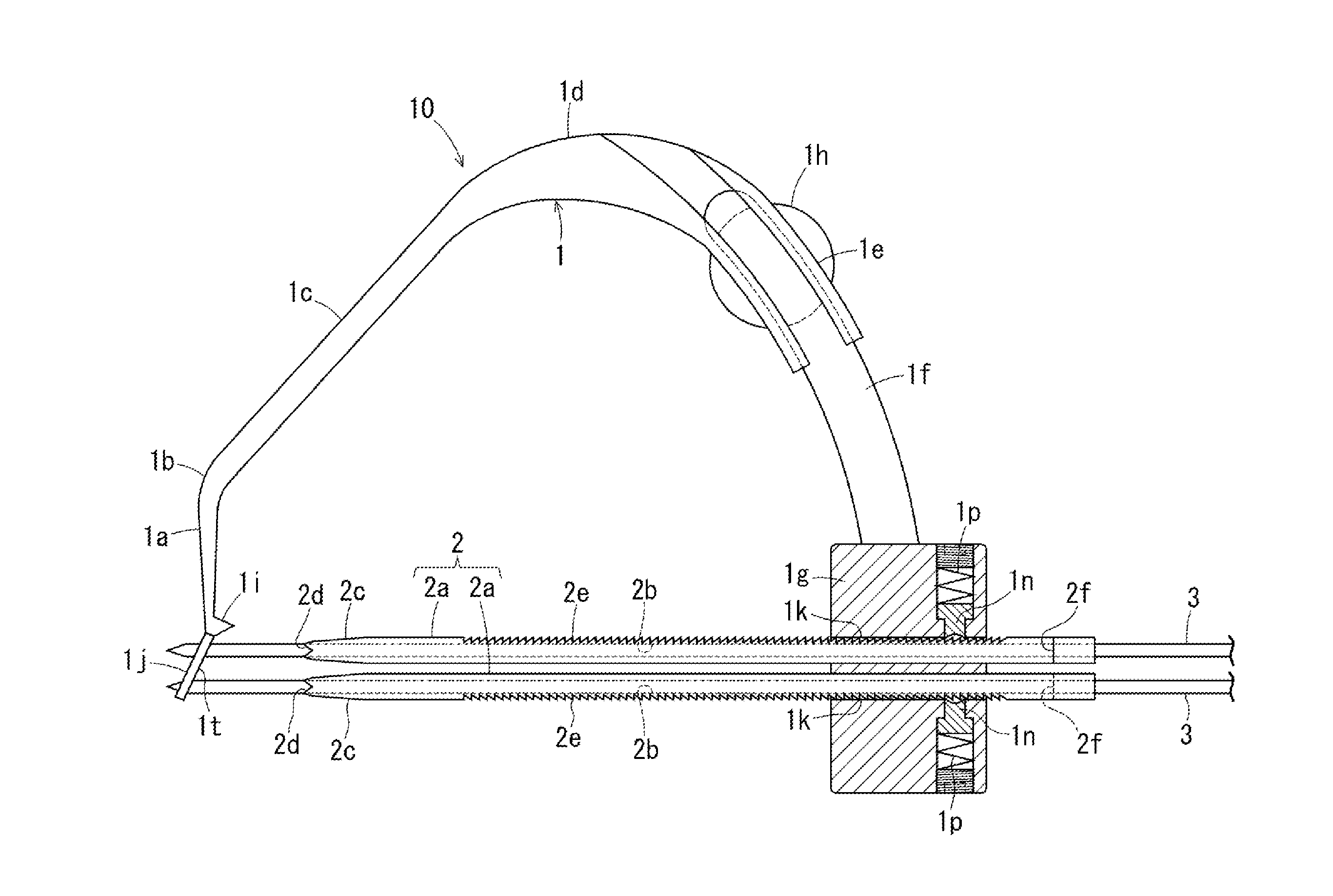
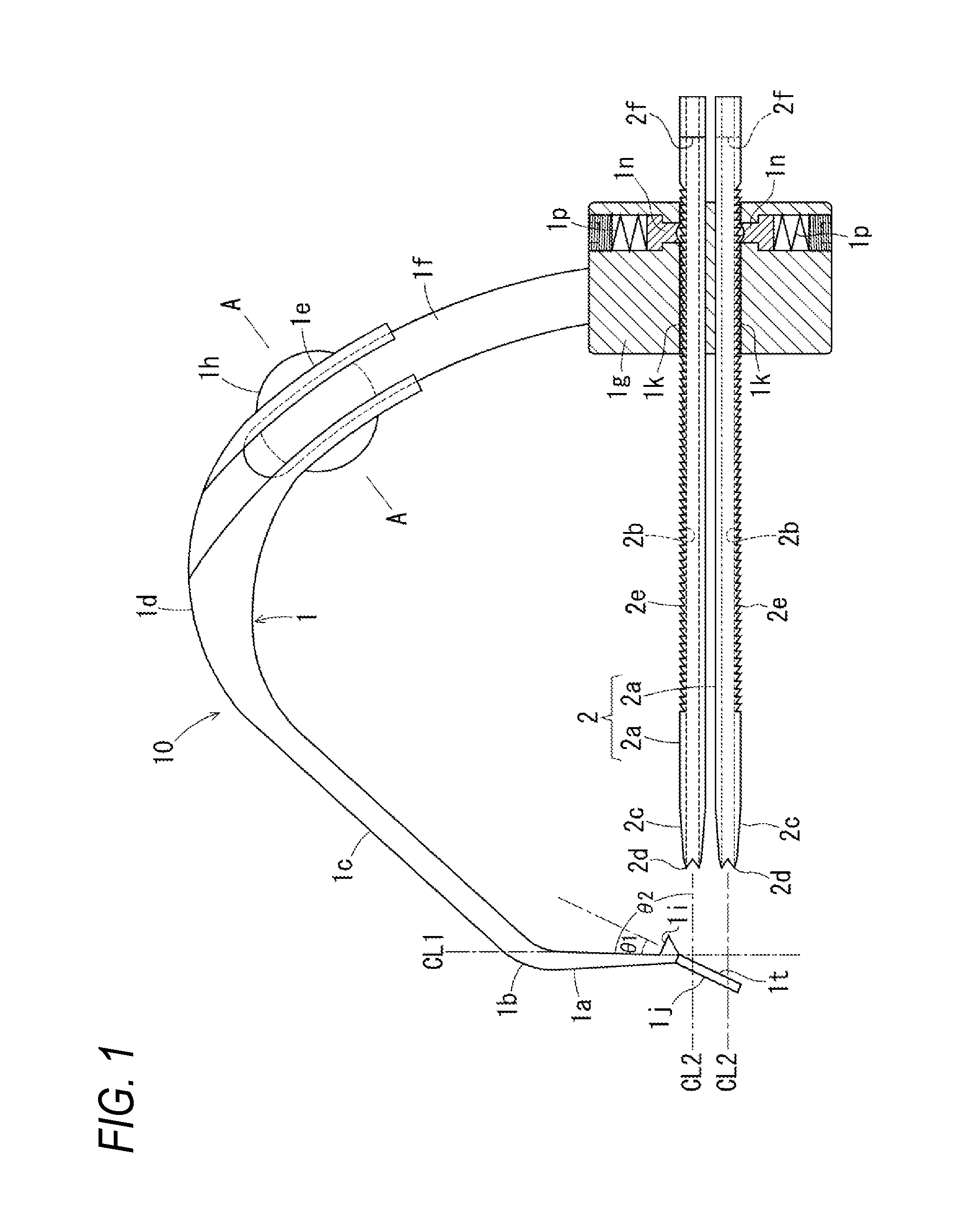
[0049]Guide pin piercing jigs according to embodiments of the present invention will be hereinafter described in detail with reference to the drawings.

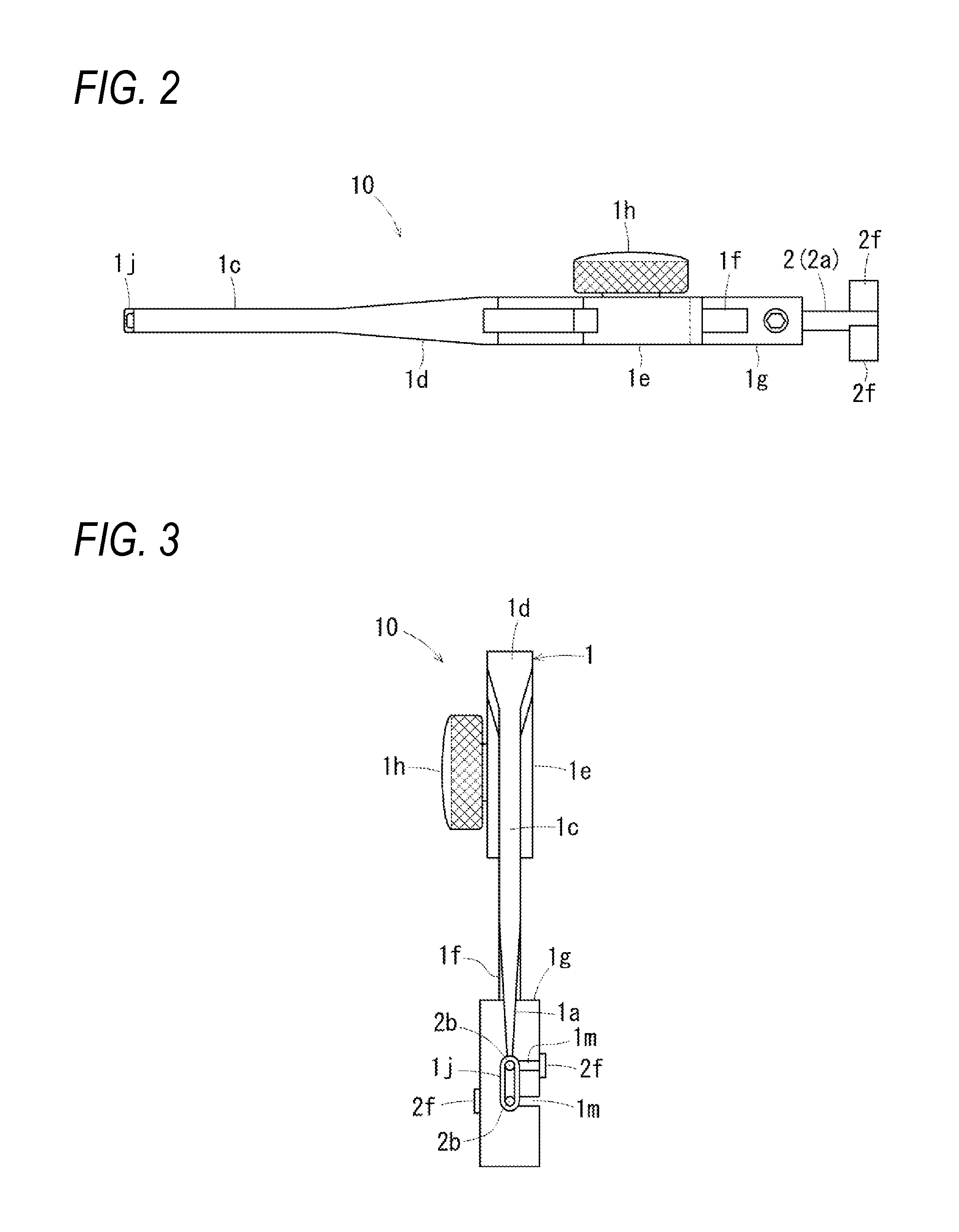
[0050]FIG. 1 is a partially sectional side view of a guide pin piercing jig according to an embodiment of the invention, FIG. 2 is a plan view of the guide pin piercing jig, FIG. 3 is a front view of the guide pin piercing jig, FIG. 4 is a rear view of the guide pin piercing jig, FIG. 5 is an end view of cutting FIG. 1 along the line A-A, FIG. 6 is a partially sectional side of the guide pin piercing jig in which guide pins are inserted in plural respective guide pin insertion cylinders, FIG. 7 is a perspective view of one guide pin insertion cylinder, and FIG. 8 is a sectional view of part of the guide pin piercing jig and shows a state that the guide pin insertion cylinders are unlocked and are thereby made slidable rearward.

[0051]As described later, the guide pin piercing jig 10 shown in FIGS. 1-5 is to be used for piercing a shinb...


PUM


Abstract

A guide pin piercing jig includes a cylinder unit and a frame having a positioning projection at a tip thereof, in which the cylinder unit has plural parallel guide pin insertion cylinders and tentative fixing unit and is attached to the frame slidably so as to be directed to the tip of the frame. It becomes possible to pierce living body bone with plural guide pins for hollow drills to a proper portion of a living body bone in a proper direction with parallel arrangement to form a bone tunnel that has a rectangular or elliptical opening and is suitable for tendon transplantation.

Description

BACKGROUND OF THE INVENTION[0001]1. Technical Field[0002]The present invention relates to a jig to be used for piercing a living body bone with a guide pin for a boring hollow drill. More specifically, the present invention relates to a guide pin piercing jig which is used for piercing a bone of the knee joint or the like with a guide pin for a hollow drill, for example, in reconstruction of a torn anterior cruciate ligament, correctly at the position and direction according to the intention of a doctor in boring, through the bone of the knee joint or the like, by the hollow drill, a bone tunnel that is necessary to transplant a tendon acquired from another part in the knee joint or the like.[0003]2. Description of the Related Art[0004]As is well known, in reconstruction of a torn anterior cruciate ligament (ACL), it is necessary to bore, through a bone of the knee joint at a proper location, a bone tunnel that is necessary to transplant a tendon acquired from another part in the kn...

Claims


Application Information

Patent Timeline
IPC IPC(8): A61B17/17
CPCA61B17/1725A61B17/1764A61B17/1714
Inventor OKUNO, MASAKIMORII, HIROSHINADA, KATSUYAKURODA, RYOSUKE
Owner TEIJIN MEDICAL TECH CO LTD
Learn More