Osteosynthesis screw with reduced radial compression

a radial compression and screw technology, applied in the field of bone surgery, can solve the problems of increased screw tightening torque, conical head that is liable to generate lines of split, conical head that is prone to cracks in the bone mass, etc., and achieves the effect of reducing radial pressure during screw tightening, reducing radial pressure, and easy penetration

Active Publication Date: 2015-06-04
IN2BONES
View PDF5 Cites 0 Cited by
  • Summary
  • Abstract
  • Description
  • Claims
  • Application Information

AI Technical Summary

Benefits of technology

[0017]Another object of the invention is to propose an osteosynthesis screw that penetrates particularly easily.
[0018]Another object of the invention is to propose an osteosynthesis screw that can be put into place in particularly simple and fast manner.
[0019]The objects given to the invention are achieved with the help of an osteosynthesis screw formed by a core provided externally with a helical thread, said screw having a distal penetration portion and a proximal portion forming the screw head and having a conical longitudinal section, the screw being characterized in that the proximal portion includes circular notches that are formed in the thickness of the core and in the inter-thread gaps of said proximal portion so as to reduce radial pressure during screw tightening.

Problems solved by technology

Nevertheless, that well-known advantage is accompanied by a drawback associated specifically with the increase in said screw-tightening torque associated with the conical shape, in particular of the head.
The head is in danger of causing cracks to appear in the bone mass because of the existence of a high level of radial compression force.
Those screws may have conical heads that are then liable to generate lines of split just like non-compressive osteosynthesis screws.

Method used


Image

  • Osteosynthesis screw with reduced radial compression
  • Osteosynthesis screw with reduced radial compression
  • Osteosynthesis screw with reduced radial compression

Examples


Embodiment Construction

[0025]In the description and the drawings that follow, reference is made to a non-compressive osteosynthesis screw purely by way of illustrative and non-limiting example, it being understood that the invention may naturally also be applied to a compressive osteosynthesis screw, such that the invention relates to an osteosynthesis screw in general, regardless of whether it is compressive or non-compressive.

[0026]Preferably, the screw of the invention is constituted by a non-compressive osteosynthesis screw.

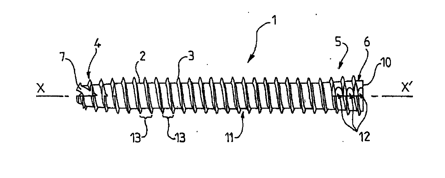
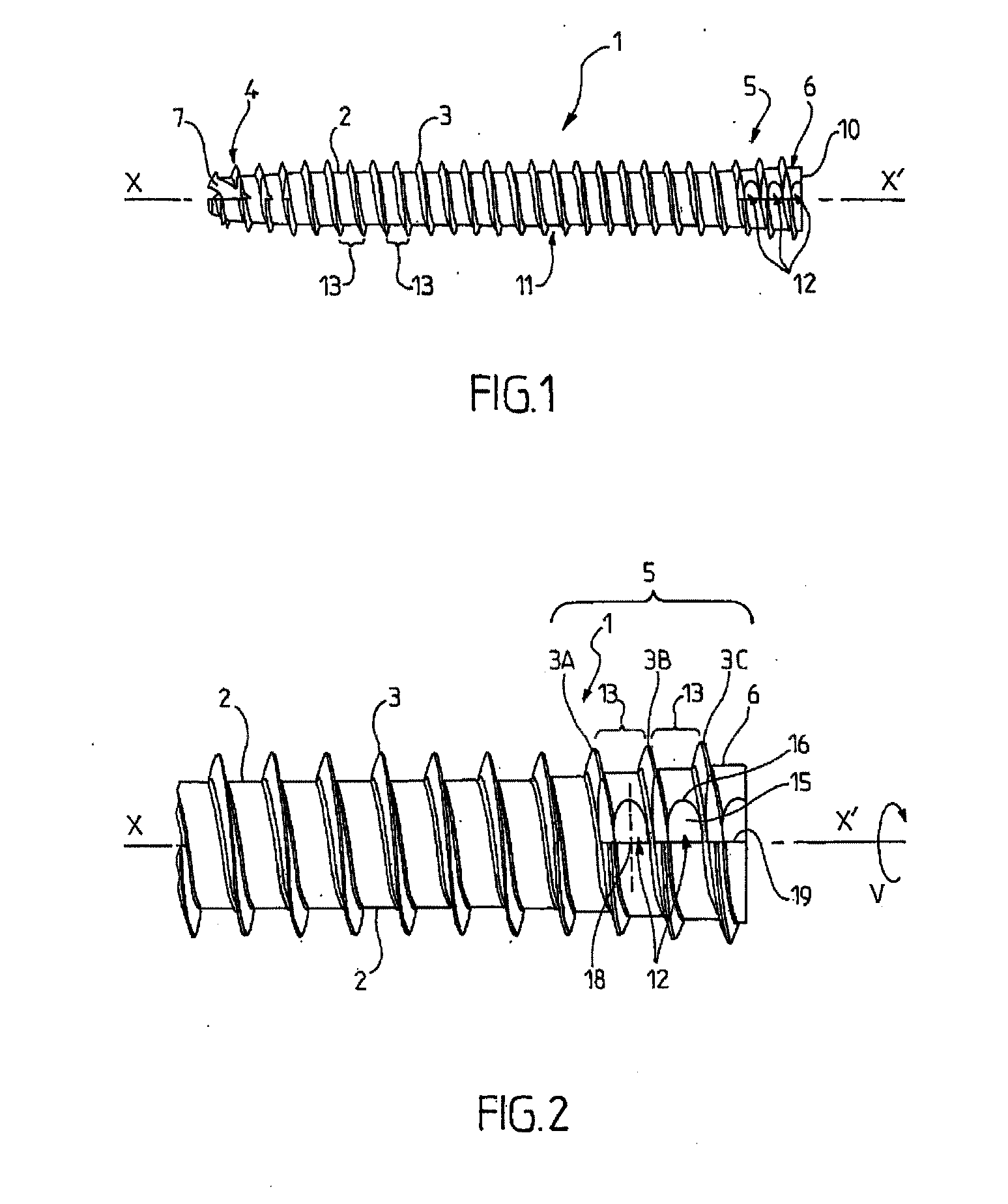
[0027]The non-compressive osteosynthesis screw 1 shown in the figures is generally in the form of an oblong screw of substantially cylindrical general shape extending along a longitudinal axis X-X′ that also defines the axis about which the screw is turned in order to penetrate into bone mass.

[0028]The osteosynthesis screw of the invention is preferably a non-compressive osteosynthesis screw 1, i.e. a screw designed to avoid generating an axial compression force suitable for bringi...


PUM


Abstract

The invention concerns an osteosynthesis screw (1) formed from a core (2) externally provided with a helical thread (3), said screw comprising a distal penetration portion and a proximal portion forming the head of the screw (6) and having a conical longitudinal section characterised in that the proximal portion comprises annular notches which are formed in the thickness of the core (2) and in the gaps between the threads of said proximal portion in such a way as to reduce the radial pressure during screwing.—Surgical device.

Description

TECHNICAL FIELD[0001]The present invention relates to the technical field of bone surgery, and in particular to osteosynthesis screws in general, which may be compressive or non-compressive, serving to apply compression or merely to stabilize or hold stationary the positioning of bones without compressing them.[0002]The present invention relates to osteosynthesis screws in general, regardless of whether they are compressive or non-compressive, and in particular to a screw formed by a core having an external helical thread, said screw having a distal penetration portion and a proximal portion forming a screw head and having a cross-section that is conical.PRIOR ART[0003]It is already known to have recourse to osteosynthesis screws that are designed to avoid applying compression to bone masses in which they have been screwed, unlike conventional osteosynthesis screws that provide compression and that a surgeon uses specifically during screw tightening to cause fractured bone portions ...

Claims


Application Information

Patent Timeline
Patent Type & Authority Applications(United States)
IPC IPC(8): A61B17/86
CPCA61B17/8625A61B17/8605A61B17/863A61B17/864A61B17/8635A61B17/8615
Inventor GAUNEAU, BERTRAND XAVIER FRANCFOURCAULT, ERIC STEPHANEGIET, JEAN-CHRISTOPHE ALAIN
Owner IN2BONES
Why Eureka
Try Eureka