Speed change algorithim for a continuous flow blood pump

Active Publication Date: 2015-06-04
HEARTWARE INC
View PDF1 Cites 82 Cited by
  • Summary
  • Abstract
  • Description
  • Claims
  • Application Information

AI Technical Summary

Benefits of technology

[0012]The method may further include the step of setting the first and second speeds and the first and second periods by choosing one of a plurality of preset operating profiles and actuating a control circuit associated with the pump to operate the pump according to the chosen profile. The plurality of preset operating profiles may include a first preset operating profile in which the first period is about 10 seconds, the ramp-down period, the second period, and the ramp-up period total about 5 seconds, and the second speed is about 80% of the first speed.

Problems solved by technology

This can be due to continuous ventricular unloading and may affect aortic valve opening behavior during VAD support.
Long-term VAD support can increase t

Method used


Image

  • Speed change algorithim for a continuous flow blood pump
  • Speed change algorithim for a continuous flow blood pump
  • Speed change algorithim for a continuous flow blood pump

Examples


Embodiment Construction

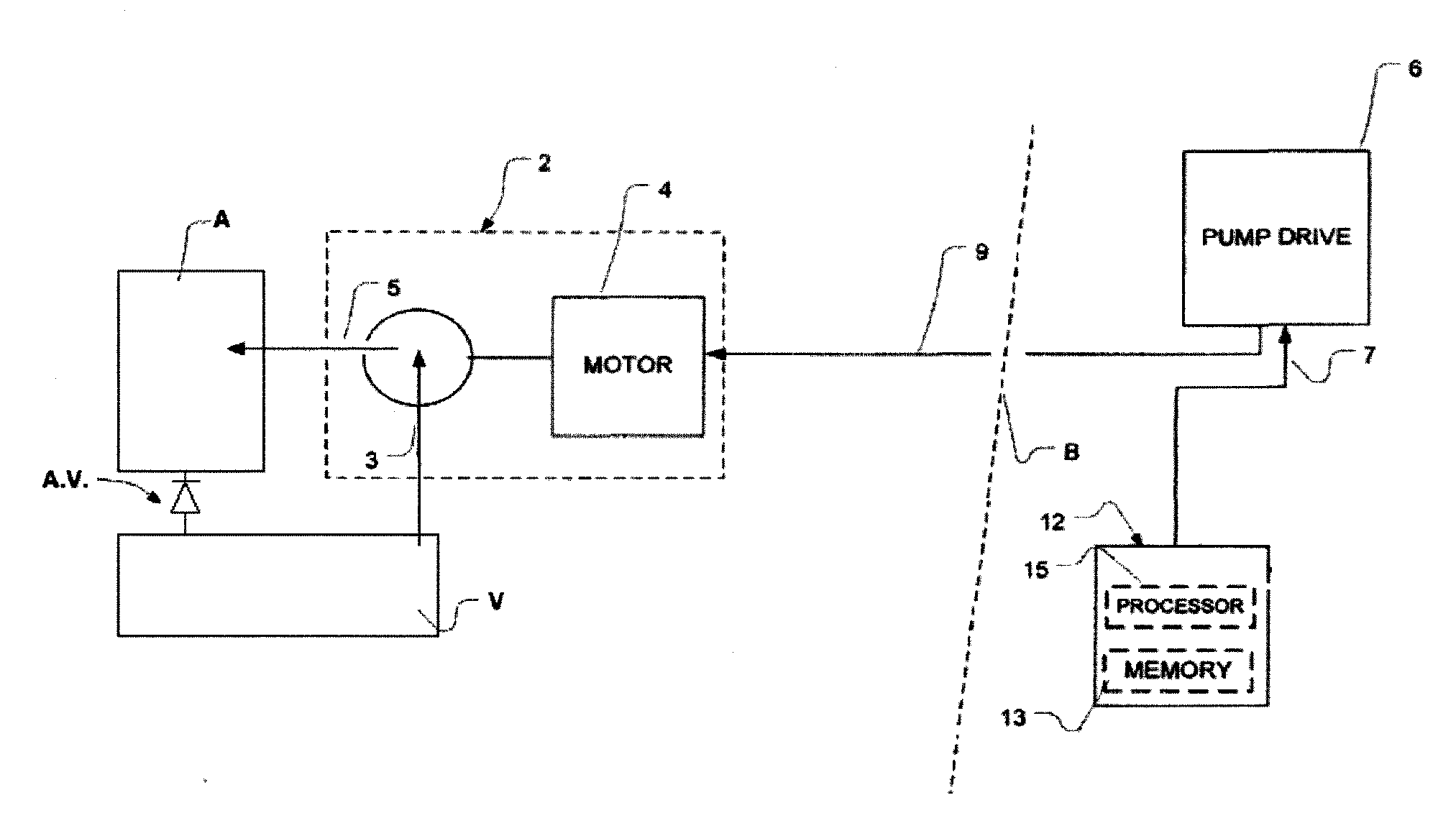
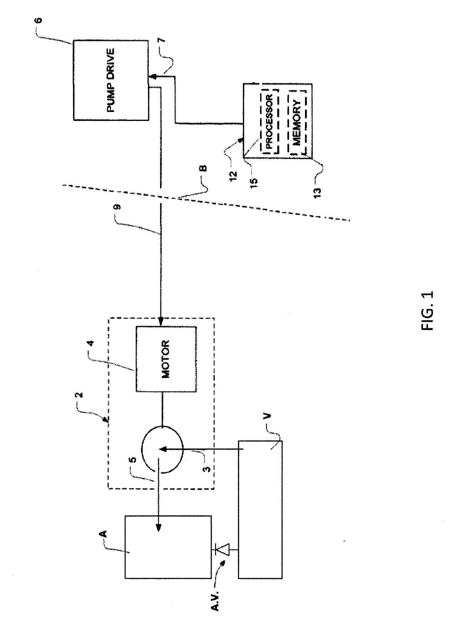
[0016]A VAD according to one embodiment of the invention (FIG. 1) includes an implantable rotary pump 2, incorporating a motor 4. As used in this disclosure, the term “rotary pump” refers to a pump which incorporates a pumping element mounted for rotation in a housing. Most typically, the pump 2 is a rotary impeller pump having an impeller mounted within the housing, so that the spinning motion of the impeller transfers momentum to the fluid to be pumped. Although the pump 2 and motor 4 are depicted as separate components for clarity of illustration in FIG. 1, in practice these components can be closely integrated with one another. For example, the impeller of the pump 2 may serve as the rotor of the motor 4. Most typically, the motor 4 is a multi-phase alternating current, permanent magnet motor arranged to drive the impeller of the pump 2 at a rotational speed proportional to the frequency of the current supplied to the motor 4. Pump 2 has a fluid inlet 3 and a fluid outlet 5. The...


PUM


Abstract

A ventricular assist device (“VAD”) includes a continuous-flow pump (2) implantable in fluid communication with a ventricle (V) and an artery (A) of a patient to assist blood flow from the ventricle to the artery. The VAD also includes a control circuit (12) connected to the pump, the control circuit being configured to direct the pump to operate in a series of cycles. Each cycle may include (i) pumping blood at a first speed (RPM1) and at a first flow rate during a first period (t1); then (ii) decreasing the speed of the pump from the first speed to a second speed (RPM2) during a ramp-down period (tRD); then (iii) pumping blood at the second speed and at a second flow rate during a second period (t2); and then (iv) increasing the speed of the pump from the second speed to the first speed during a ramp-up period (tRU).

Description

CROSS-REFERENCE TO RELATED APPLICATIONS[0001]The present application claims priority of the filing date of U.S. Provisional Application No. 61 / 656,342, filed Jun. 6, 2012, entitled SPEED CHANGE ALGORITHM FOR A CONTINUOUS FLOW BLOOD PUMP, the disclosure of which is hereby incorporated herein by reference.BACKGROUND OF THE INVENTION[0002]A ventricular assist device (“VAD”) is a device which is used to assist the heart of a mammalian subject such as a human patient. A typical VAD Includes a pump which is implanted in the body of the subject. The pump typically has an inlet connected to a source of blood to be circulated, and an outlet connected to an artery. Most typically, the inlet of the pump is connected to the interior of the left ventricle and the outlet of the pump is connected to the aorta, so that the pump operates in parallel with the left ventricle to impel blood into the aorta. The pump may be a miniature rotary impeller pump having an impeller disposed in a pump housing an...

Claims


Application Information

Patent Timeline
IPC IPC(8): A61M1/10
CPCA61M1/1086A61M2205/3365A61M2205/3334G16H40/63A61M60/148A61M60/422A61M60/178A61M60/226A61M60/585A61M60/876
Inventor VOSKOBOYNIKOV, NEILGRAHAM, JOEL
Owner HEARTWARE INC
Why Eureka
Try Eureka