System and Method for Detecting an At-Fault Combustor

a combustor and fault technology, applied in the field of gas turbines, can solve problems such as affecting machine availability, failure to operate completely, and operating outside of an acceptable performance rang

Active Publication Date: 2015-06-11
GENERAL ELECTRIC CO
View PDF3 Cites 21 Cited by
  • Summary
  • Abstract
  • Description
  • Claims
  • Application Information

AI Technical Summary

Problems solved by technology

Over time, various factors including thermal cycling, vibrations and/or pressure pulses within the combustor may result in combustion component degradation, thus resulting in a combustor that...

Method used


Image

  • System and Method for Detecting an At-Fault Combustor
  • System and Method for Detecting an At-Fault Combustor
  • System and Method for Detecting an At-Fault Combustor

Examples


Embodiment Construction

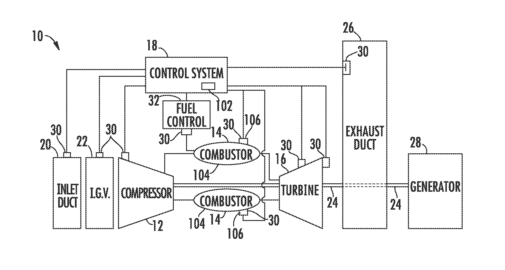
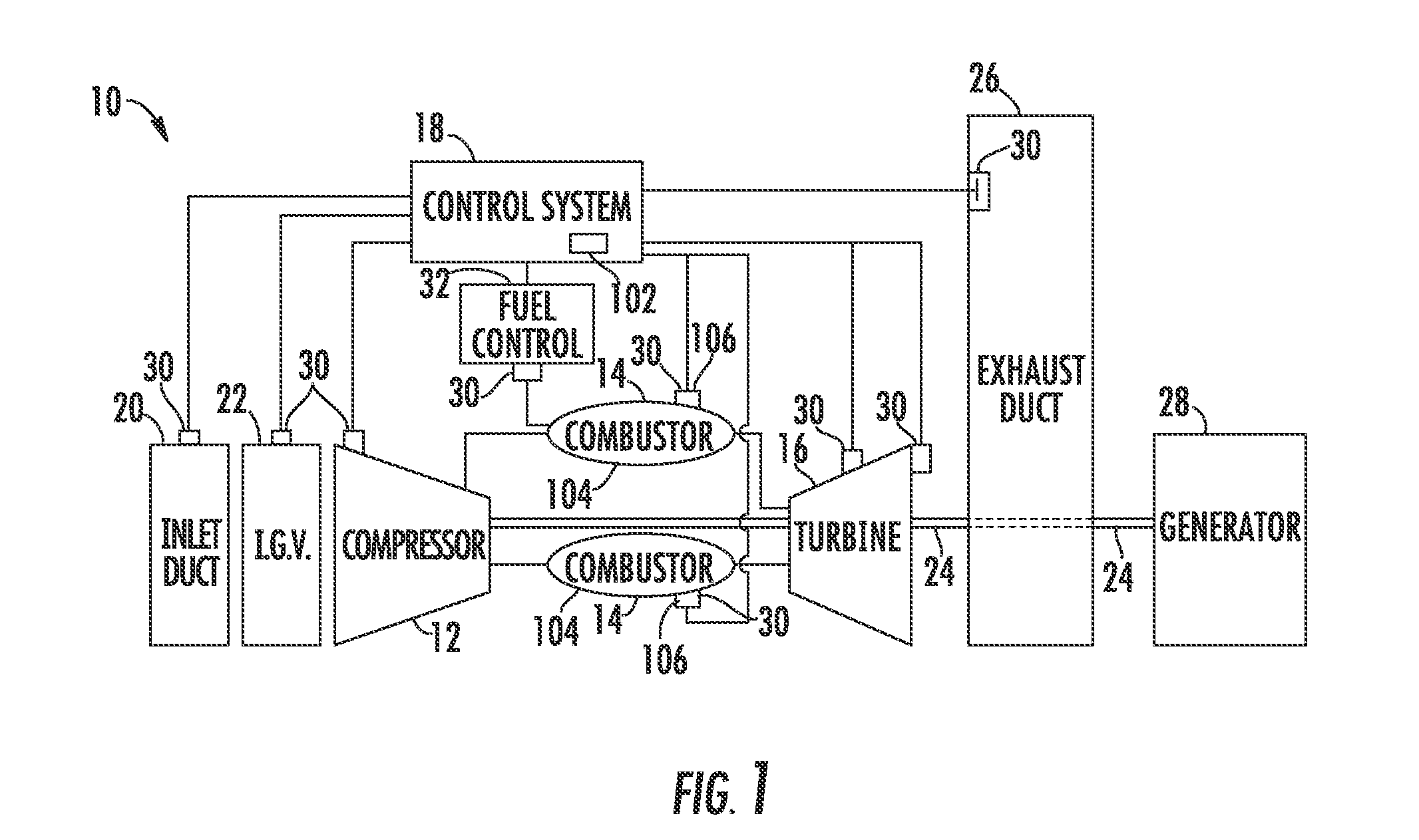
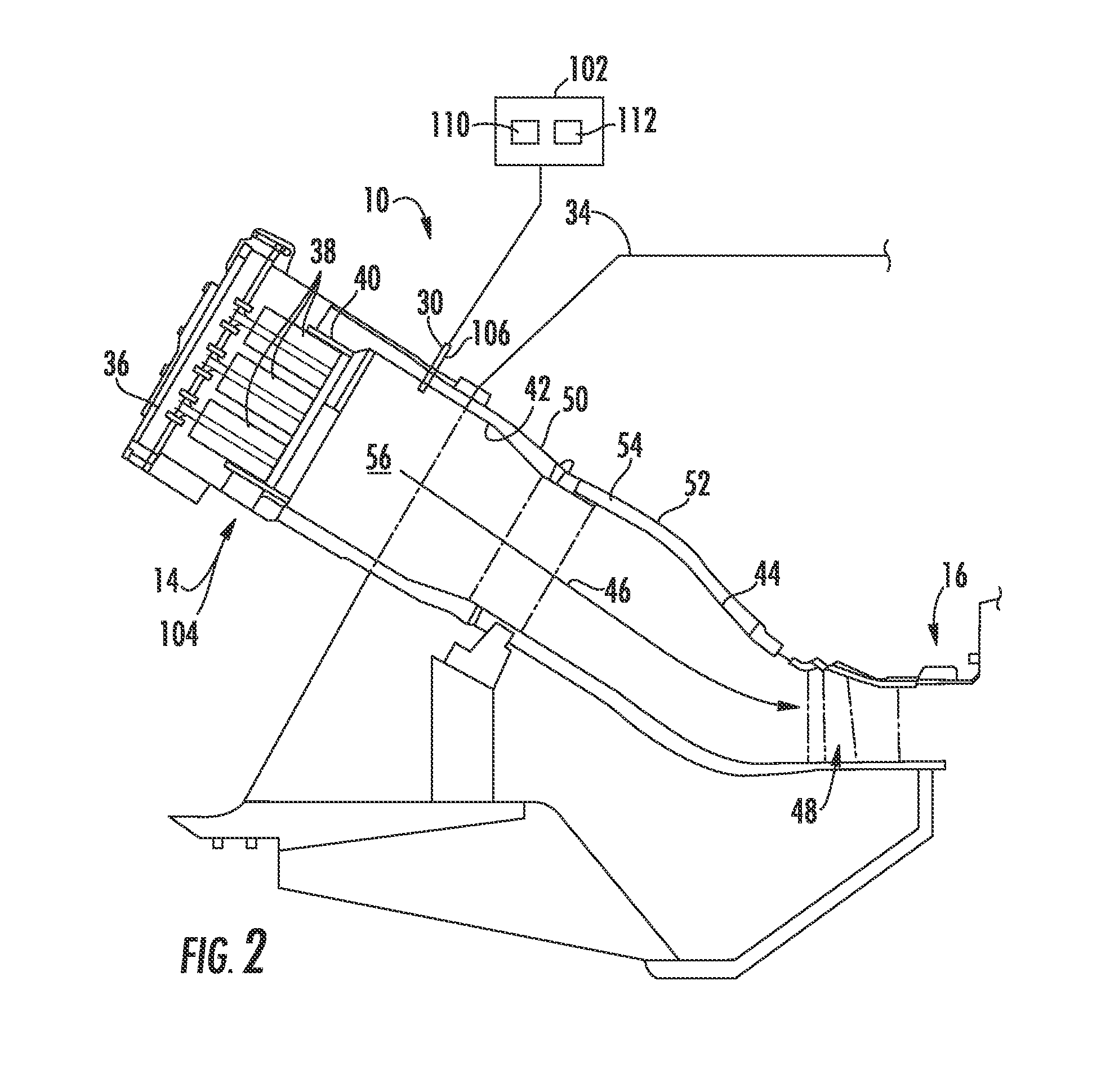
[0018]Reference will now be made in detail to present embodiments of the invention, one or more examples of which are illustrated in the accompanying drawings. The detailed description uses numerical and letter designations to refer to features in the drawings. Like or similar designations in the drawings and description have been used to refer to like or similar parts of the invention.

[0019]As used herein, the terms “first”, “second”, and “third” may be used interchangeably to distinguish one component from another and are not intended to signify location or importance of the individual components. The terms “upstream” and “downstream” refer to the relative direction with respect to fluid flow in a fluid pathway. For example, “upstream” refers to the direction from which the fluid flows, and “downstream” refers to the direction to which the fluid flows. When introducing elements of aspects of the present disclosure or the embodiments thereof, the articles “a,”“an,”“the,” and “said”...


PUM


Abstract

A system for detecting an at-fault combustor includes a sensor that is configured to sense combustion dynamics pressure data from the combustor and a computing device that is in electronic communication with the sensor and configured to receive the combustion dynamics pressure data from the sensor. The computing device is programmed to convert the combustion dynamics pressure data into a frequency spectrum, segment the frequency spectrum into a plurality of frequency intervals, extract a feature from the frequency spectrum, generate feature values for the feature within a corresponding frequency interval over a period of time, and to store the feature values to generate a historical database. The computing device is further programmed to execute a machine learning algorithm using the historical database of the feature values to train the computing device to recognize feature behavior that is indicative of an at-fault combustor.

Description

FIELD OF THE INVENTION[0001]The present invention generally involves a gas turbine. More specifically, the invention relates to a system and method for detecting an at-fault combustor during operation of the gas turbine.BACKGROUND OF THE INVENTION[0002]A turbomachine, such as a gas turbine, generally includes an inlet section, a compressor section, a combustion section that includes a plurality of combustors, a turbine section and an exhaust section. The inlet section cleans and conditions a working fluid (e.g., air) and supplies the working fluid to the compressor section. The compressor section progressively compresses the working fluid and supplies a high pressure compressed working fluid to the combustors where it is mixed with a fuel and burned in a combustion chamber to generate combustion gases having a high temperature and pressure. The combustion gases flow along a hot gas path into the turbine section where they expand to produce work. For example, expansion of the combust...

Claims


Application Information

Patent Timeline
IPC IPC(8): G01M15/14F23R3/00F23M11/00
CPCG01M15/14F23R2900/00005F23R3/00F23M11/00F05D2260/80F23N5/16F23N5/242F23N2223/48F23N2223/54F23N2241/20Y02T50/60
Inventor PATRICK, ROMANOLEMMON, MATTHEW FRANCISNANDA, SUBRATWHITE, JONATHAN DAVIDPANDEY, ACHALESH KUMAR
Owner GENERAL ELECTRIC CO
Why Eureka
Try Eureka