Method and System for Testing Operational Integrity of a Drilling Rig

a drilling rig and operational integrity technology, applied in the direction of seismology for waterlogging, instruments, borehole/well accessories, etc., can solve the problem of increasing the demand for system reliability

Inactive Publication Date: 2015-06-11
UNIV OF CONNECTICUT +1
View PDF21 Cites 53 Cited by
  • Summary
  • Abstract
  • Description
  • Claims
  • Application Information

AI Technical Summary

Problems solved by technology

The expense of equipment or parts employed in mechanical systems, e.g., a drilling rig, as well as the cost associated with typical corresponding mechanical operations drive, an increasing demand for system reliability.

Method used


Image

  • Method and System for Testing Operational Integrity of a Drilling Rig
  • Method and System for Testing Operational Integrity of a Drilling Rig
  • Method and System for Testing Operational Integrity of a Drilling Rig

Examples


Embodiment Construction

[0027]A description of example embodiments of the invention follows.

[0028]Common techniques for drilling rig operation monitoring use measured parameters such as speed, rate of penetration, drill bit location etc. More advanced techniques used for monitoring drilling rigs and other mechanical systems include analyzing other measured parameters or signals, such as vibration, motor current, load, wear debris, etc. Herein, new monitoring approaches are disclosed.

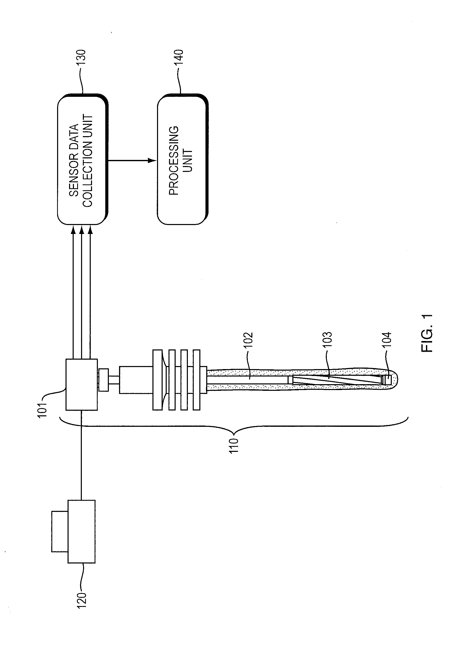
[0029]FIG. 1 describes a system overview according to an example embodiment of the present invention. A drilling rig 110 includes a top drive 101, a drill pipe 102, and a drill bit 104. The drill bit 104 is a cutting tool that is configured to dig through the earth's crust as it is caused to rotate by an induction motor (not shown) in the top drive 101. The induction motor is mechanically coupled to the drill bit 104 through gears (not shown), bearings (not shown), and a drill shaft 103 or drill string. The induction motor is u...


PUM


Abstract

A method of testing and monitoring operational integrity of a drilling rig is described. The method includes operating the drilling rig in a non-drilling mode at a sequence of different phases including an acceleration phase, a constant speed phase, and a decelerating phase, collecting sensor data associated with one or more components of the drilling rig while the drilling is operated in the non-drilling mode at the sequence of different phases, and analyzing the collected sensor data to determine the operational integrity of the drilling rig. The analyzed data, together with previously stored historical data is used to estimate the life expectancy of the rig and monitor, plan, control, or report maintenance activity for the drilling rig, top drive, or any other system.

Description

BACKGROUND OF THE INVENTION[0001]The expense of equipment or parts employed in mechanical systems, e.g., a drilling rig, as well as the cost associated with typical corresponding mechanical operations drive, an increasing demand for system reliability. Efficient monitoring and early defect diagnosis of vital components of mechanical systems are relevant factors in achieving reliable and trouble-free operations, e.g., drilling operation in the case of a drilling rig.SUMMARY OF THE INVENTION[0002]According to one aspect, a method and corresponding system of testing and monitoring operational integrity of a drilling rig are described. The method includes operating the drilling rig in a non-drilling mode at a sequence of different phases including an acceleration phase, a constant speed phase, and a decelerating phase, collecting sensor data associated with one or more components of the drilling rig while the drilling is operated in the non-drilling mode at the sequence of different pha...

Claims


Application Information

Patent Timeline
Patent Type & Authority Applications(United States)
IPC IPC(8): G01M99/00E21B41/00
CPCE21B41/00G01M99/008G01M13/028G01M13/045
Inventor GAO, ROBERT X.WANG, JINJIANGYAN, RUQIANGELLIS, BRIAN CHARLESSMITH, BOONE ELBERTPUENTE, JOSE ABELARDO SANCHEZ
Owner UNIV OF CONNECTICUT
Why Eureka
Try Eureka