Keyboard projection system with image subtraction

a projection system and keyboard technology, applied in the field of keyboard projection system, can solve the problems of affecting the portability of the product,

Inactive Publication Date: 2015-06-11
CTX VIRTUAL TECH
View PDF3 Cites 14 Cited by
  • Summary
  • Abstract
  • Description
  • Claims
  • Application Information

AI Technical Summary

Benefits of technology

[0016]The object of the present invention is to provide a device which, by virtue of its design and components, satis

Problems solved by technology

However, although such a keyboard solution is compact and portable, the portion of the display screen which is used by the keyboard when it is displayed, takes away from the displaying area of the screen.
However, such conventional systems generally require a bulky projection device and therefore do not provide for convenience of portability for the user.
Furthermore, conventional laser projection devices require the absolute precise alignment of the camera, laser projection and IR beam in order to properly factory calibrate the device in a stored and fixed array structure at assembly time not allowing for any movement and causing many failures after the customer receipt of said product.
Furthermore, projection devices known to the Applicant are limited to show the user's keystrokes on an external device connected to the projection device via Bluetooth™ or via a Universal Serial Bus (USB) connector, preventing the user from receivi

Method used


Image

  • Keyboard projection system with image subtraction
  • Keyboard projection system with image subtraction
  • Keyboard projection system with image subtraction

Examples


first embodiment

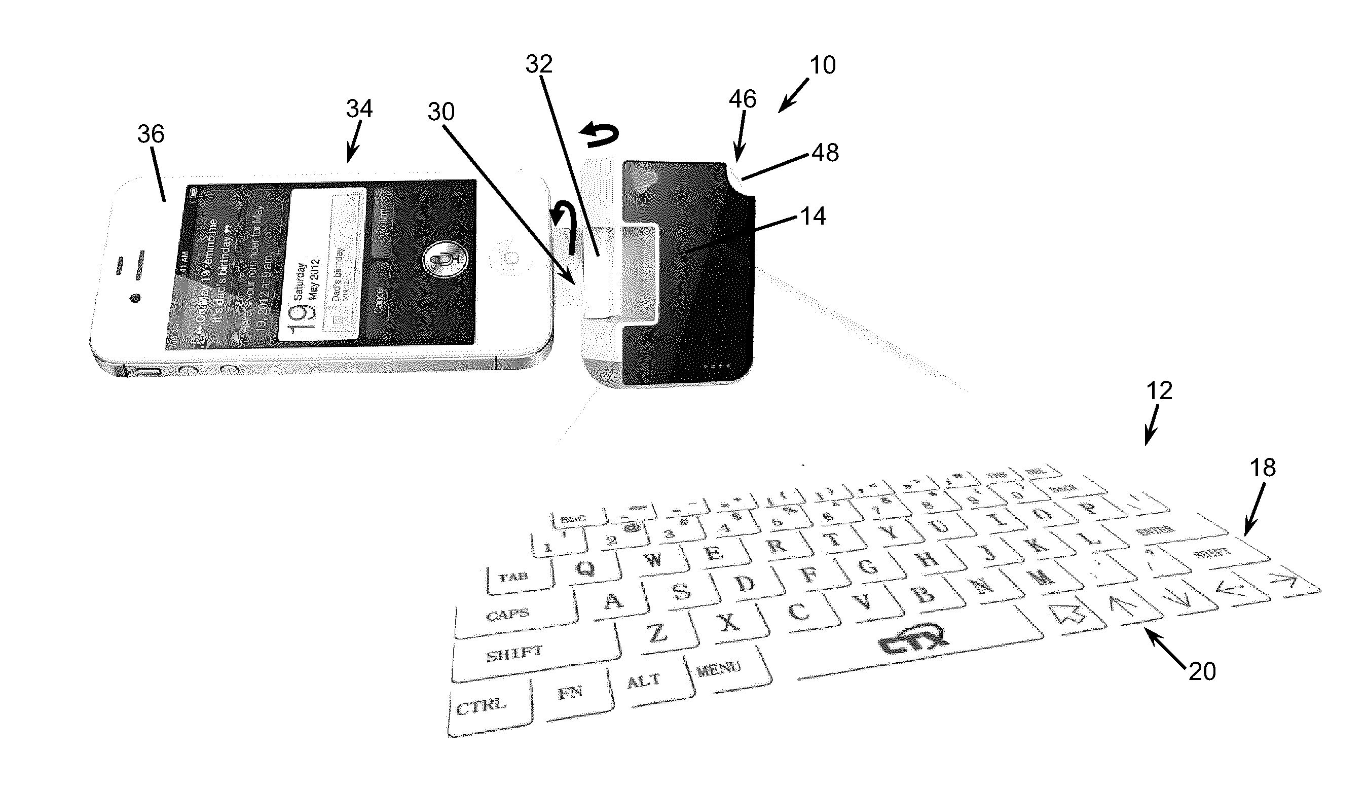
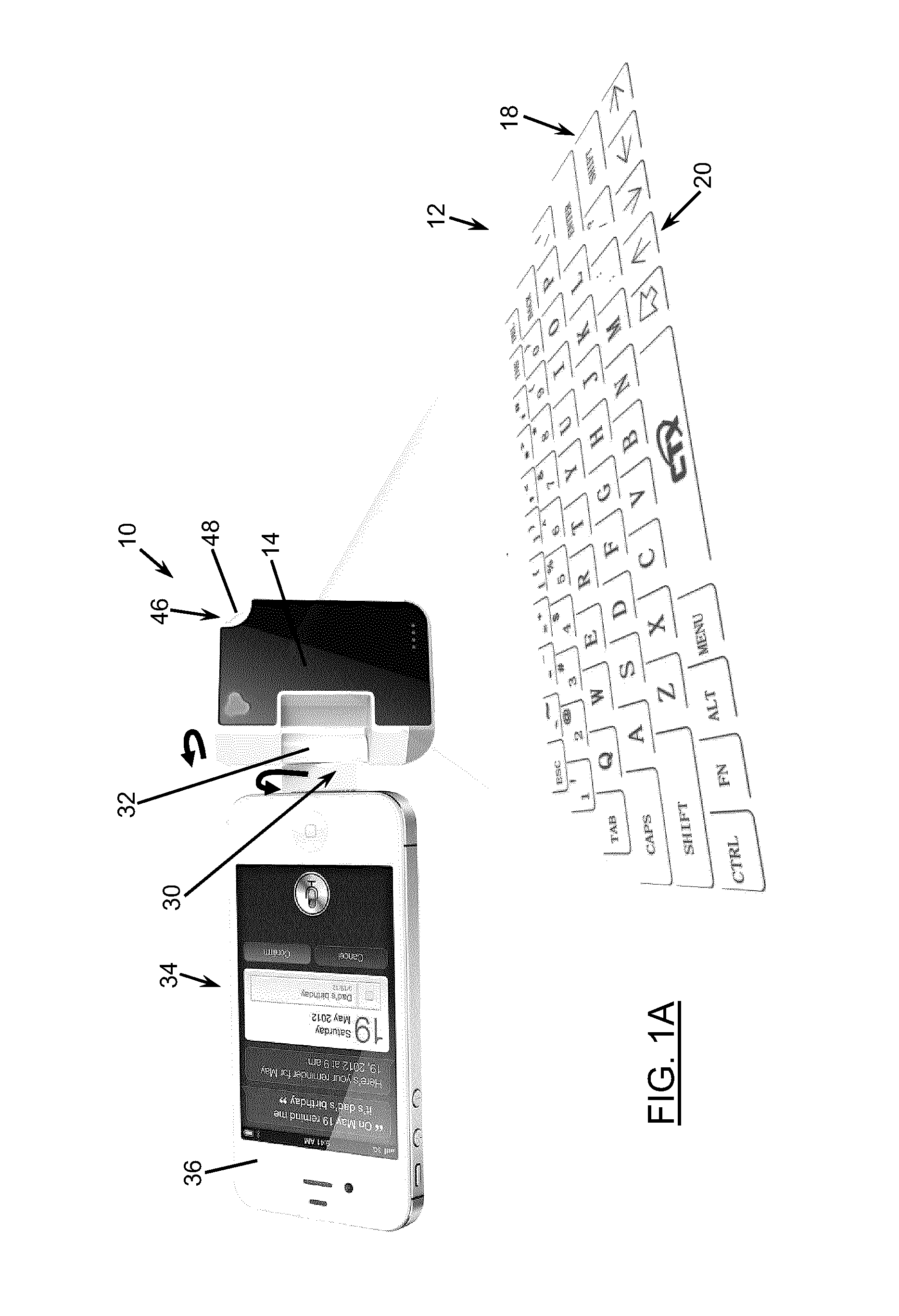
[0081]FIGS. 1A and 4 show the device 10, according to the present invention, where the communication means 30 is provided by a hard-wire connector 32. The connector 32 is pivotally mounted on the device 10 with friction grip so as to further support the smartphone 36 and allow an angular adjustment thereof.

second embodiment

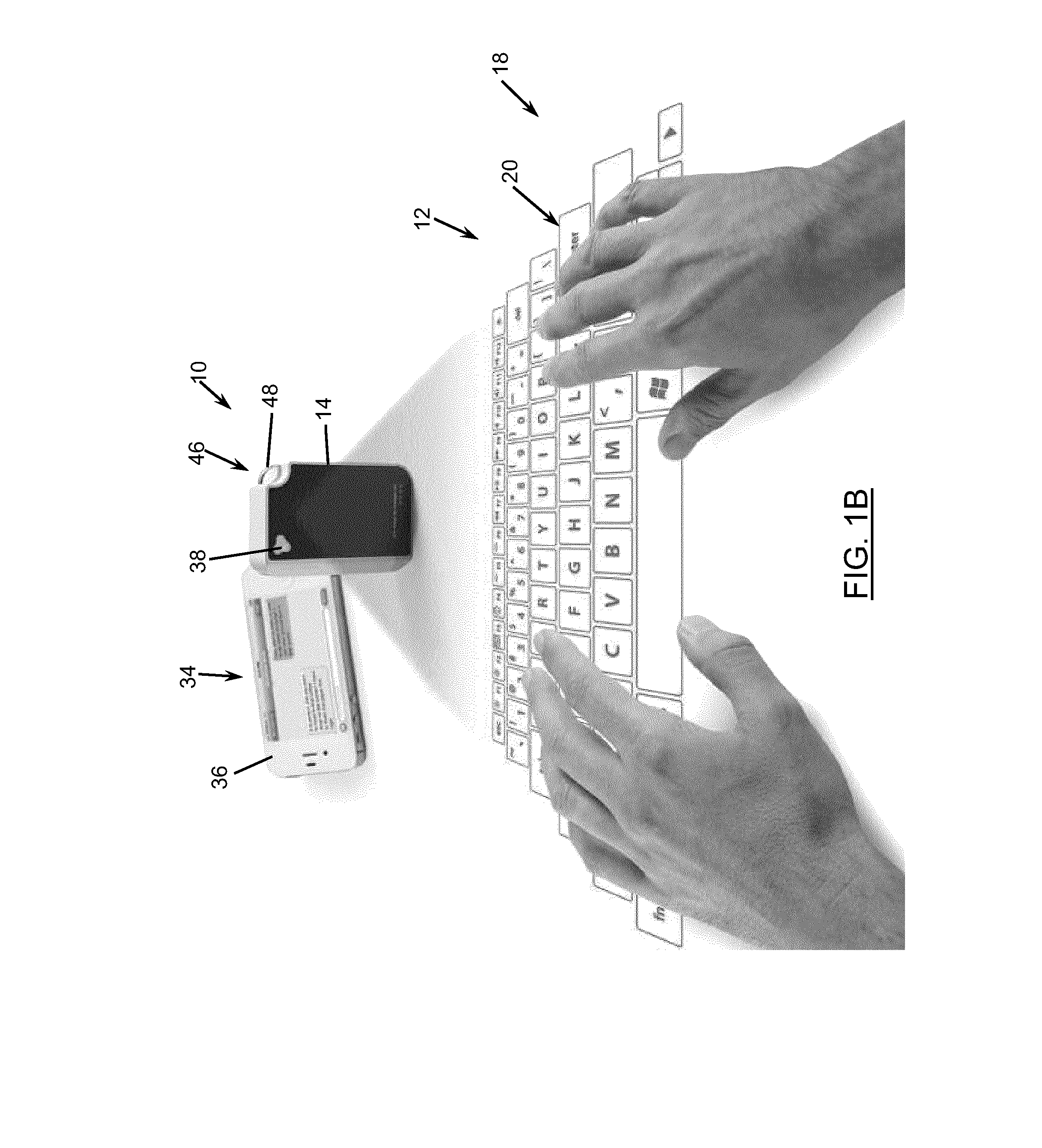
[0082]FIGS. 1B, 2 and 3, as well as FIG. 5A, 5B and FIG. 10A to 10E, show the device 10, according to the present invention, where the communication means 30 is provided a wireless communication module 33, using Bluetooth™, which is embedded in the PCBA 28.

third embodiment

[0083]FIG. 14A to 17F show the device 10, according to the present invention which also comprises communication means 30 provided by a wireless communication module 33, using Bluetooth™, which is embedded in the PCBA 28.

[0084]The device 10 further comprises the following components, for all of the first embodiment shown in FIGS. 1A and 4, the second embodiment shown in FIGS. 1B, 2 and 3, as well as the third embodiment shown in FIG. 14A to 17F: an On / Off switch 38, a battery 40, and a user interface 42, including not only the projected keyboard system (keyboard 20 with capture 22 and processing 26), but also an organic light-emitting diode (OLED) display screen 42, and a speaker 44. The device 10 further comprises an attachment component 46, such as ring 48, which allows attaching a key chain 50, as depicted in FIG. 5. Furthermore, the IR module 25 comprises an infrared (IR) light diode and a line generating lens.

[0085]It is to be understood that the computing device 34, may be a PD...


PUM


Abstract

A method for detecting a keystroke operated on a projected keyboard, and an associated device are disclosed. A first image and a second image of the projected keyboard are captured. Preferably, while the first image is taken, an infrared (IR) beam is projected on the keyboard, and while the second image is taken, the IR beam is switched off. The second image is subtracted from the first image to remove noise and detect a difference between the first and second image. The location where the difference is detected is associated with the keystroke. The location of the keystroke is determined in relation to the projected image of the keyboard. The location is then associated with a key of the keyboard based on a keyboard layout stored in a memory. A command signal corresponding to the key is then generated for transmittal to the computing device.

Description

FIELD OF THE INVENTION[0001]The present invention relates to a keyboard projection system and method. The present also relates to a calibration system and method for the keyboard projection system.BACKGROUND OF THE INVENTION[0002]Standard keyboards are generally provided by a device having an arrangement of keys, which can be pressed on to allow a user to enter input information into a computer or the like. A keyboard may be provided by a standalone device or it may be made as part of the computer, such as in the case of some laptop (or “notebook”) computers, personal digital assistants (PDA) and smartphones.[0003]Also known in the art are virtual keyboards provided on a touch screen, where a graphical image of a keyboard appears on the touch screen which then detects a touching action on the screen and its location in order to associate the action with one of the keys of the keyboard. Such keyboards are generally useful for portability and travel, for devices such as tablet compute...

Claims


Application Information

Patent Timeline
IPC IPC(8): G06F3/02
CPCG06F3/0202G06F3/0426G06F1/1632G06F1/1684G06F3/038G06F3/04883G03B21/2033
Inventor LITHWICK, DAVID S.RHEE, CLIFFORD M.
Owner CTX VIRTUAL TECH
Why Eureka
Try Eureka