Large-Area Monitoring Using Infrared Imaging System

a technology of infrared imaging and large-area monitoring, applied in the field of thermal monitoring, can solve the problems of reducing the usefulness of techniques to identify and troubleshoot problems in real-time, affecting the accuracy of image enhancement, and affecting the quality of image enhancement, etc., and achieves high temporal resolution

Inactive Publication Date: 2015-06-11
IBM CORP
View PDF6 Cites 16 Cited by
  • Summary
  • Abstract
  • Description
  • Claims
  • Application Information

AI Technical Summary

Benefits of technology

[0008]The present invention provides an imaging system and use thereof for large-area monitoring with very high temporal resolution. In one aspect of the invention, an imaging system is provided. The imaging system includes a camera equipped with curved optics having a field of view of from about 0.01 miles to about 1.5 miles; and interchangeable light filters positioned in front of the camera configured to change one or more of an intensity and an amplitude of light captured by the imaging system. The curved optics may include a hemispherical mirror configured to reflect an image of objects in front of the mirror, and the camera may be positioned facing a reflective surface of the hemispherical mirror so as to capture the image reflected in the hemispherical mirror. Alternatively, the curved optics may include a fisheye lens mounted to the camera.

Problems solved by technology

Satellite or airborne imaging techniques may be used for these applications but they tend to be expensive and lack the spatial resolution (spatial pixel size tend to be 10 meters or higher).
Furthermore, with satellite or airborne imaging the data will be acquired at large time intervals reducing the usefulness of techniques to identify and troubleshoot problems in real-time.
In many situations, the performance of individual solar panels can be diminished due to mounting errors which will affect the performance of the whole panel string and thus reduce the overall system performance.
Factors that affect individual solar panel performance can be solar sub-cell defects or wiring / interconnect issues that result in solar panel overheating.
Mounting / installation errors can also affect performance.
For example, shadowing due to nearby structures leads to reduced voltage / current performance of solar panels.
Shadowing has more of an effect in the case of series mounted solar panel strings when the resistance of the solar panels is increased (the current drops) reducing the performance of the string of panels.
Furthermore shadowing can result in voltage output fluctuations leading to unstable operation of inverters.
Either solar panel overheating (increased temperature) or shadowing can result in reduced performance.

Method used


Image

  • Large-Area Monitoring Using Infrared Imaging System
  • Large-Area Monitoring Using Infrared Imaging System
  • Large-Area Monitoring Using Infrared Imaging System

Examples


Embodiment Construction

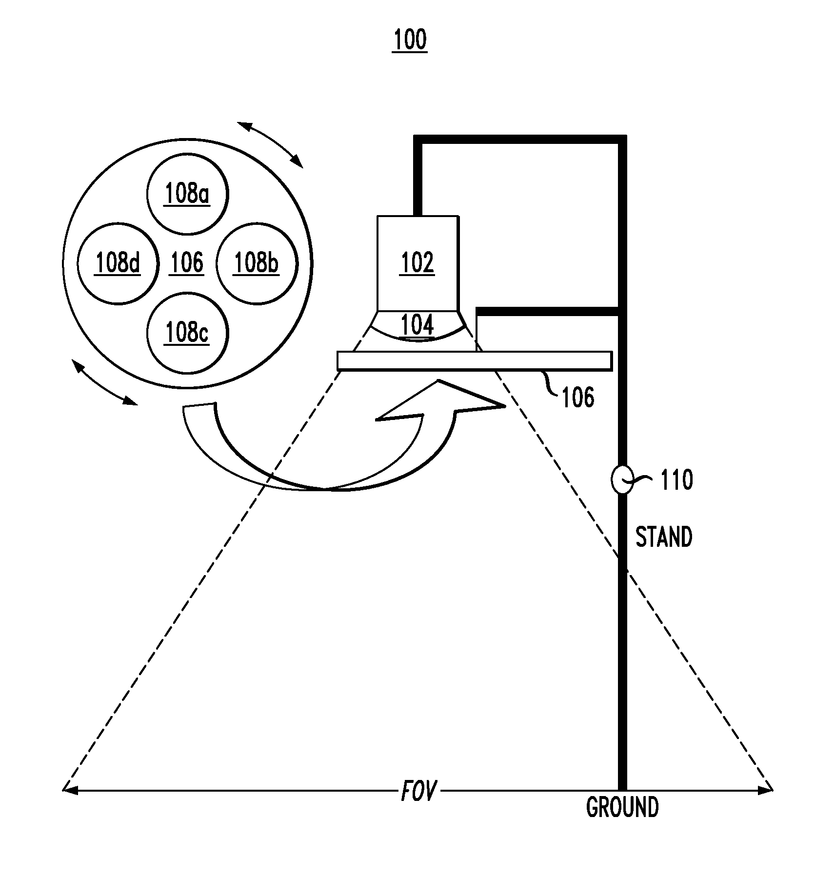
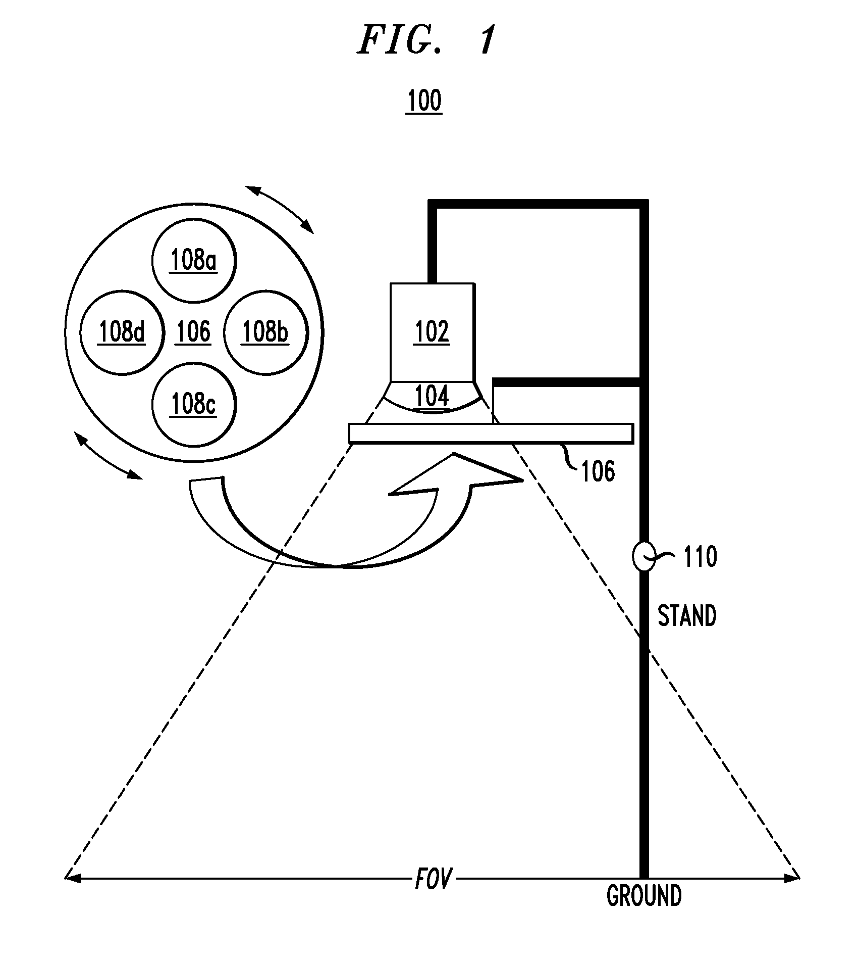
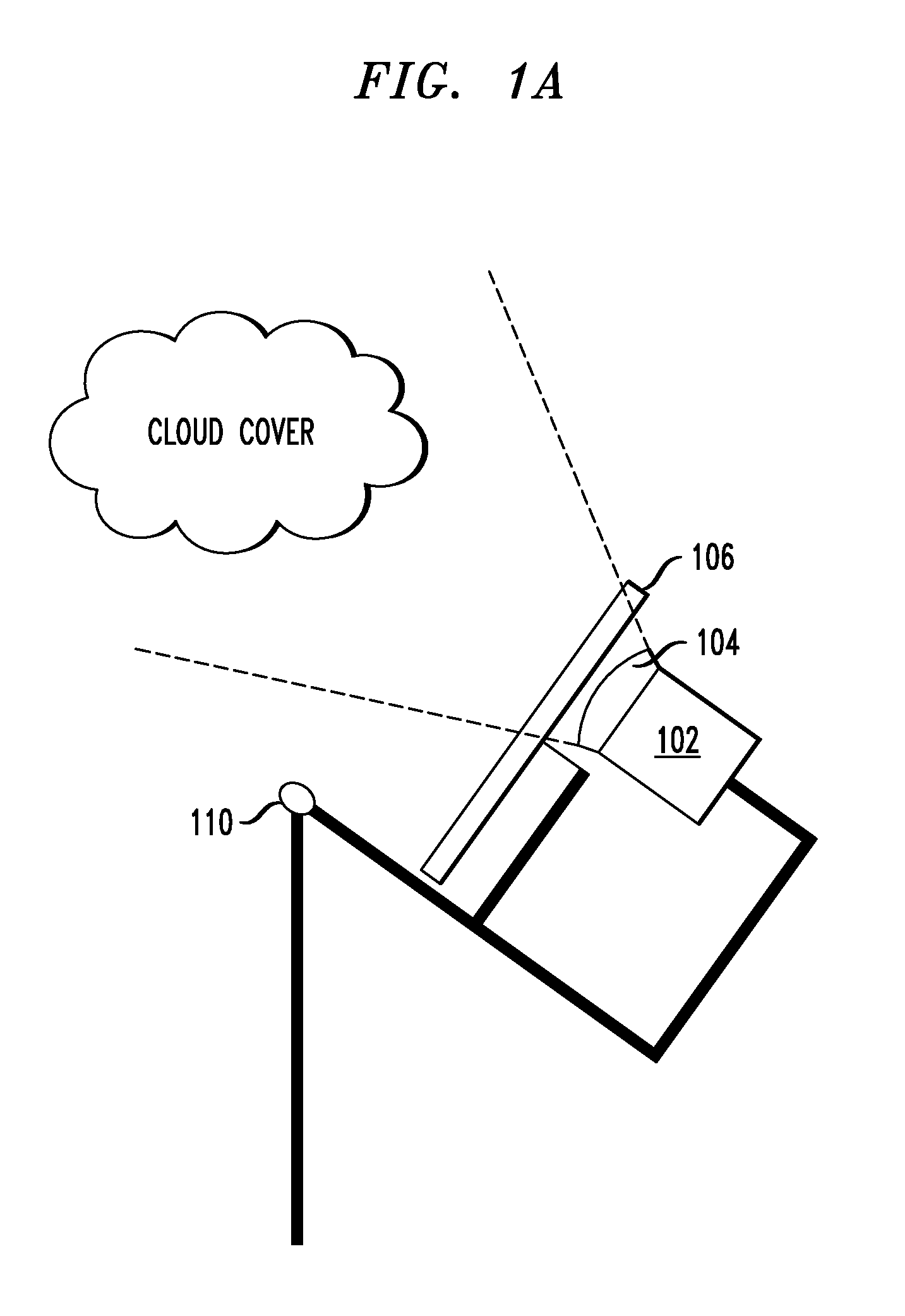
[0028]Provided herein are imaging systems and techniques for use thereof in large-area monitoring. For large-scale solar installations, localizing the panels that are underperforming is challenging as any solution / monitoring system needs to have a large area coverage and enough angular resolution and sensitivity to pinpoint the locations where problems occur. Angular resolution is the smallest area on the curved surface that can be identified. Since it is an area, it can be expressed as R ΔΘ, wherein R is the radius of the hemispherical mirror and ΔΘ is the solid angle. Advantageously, the present techniques provide such large area coverage and resolution. Furthermore, the monitoring system should also be adaptable to situations where solar panels are mounted on solar trackers that continuously rotate following the sun and are not static, allowing a continuous tracking of panels even in situations where the orientation of the panels changes. The solar tracker would rotate to follow ...


PUM


Abstract

An imaging system and use thereof for large-area monitoring with very high temporal resolution are provided. In one aspect, an imaging system includes a camera equipped with curved optics having a field of view of from about 0.01 miles to about 1.5 miles; and interchangeable light filters positioned in front of the camera configured to change one or more of an intensity and an amplitude of light captured by the imaging system. The curved optics may include a hemispherical mirror configured to reflect an image of objects in front of the mirror, and the camera may be positioned facing a reflective surface of the hemispherical mirror so as to capture the image reflected in the hemispherical mirror. Alternatively, the curved optics may include a fisheye lens mounted to the camera. An imaging network of the present imaging systems and a method for use thereof for thermal monitoring are also provided.

Description

FIELD OF THE INVENTION[0001]The present invention relates to thermal monitoring, and more particularly, to an (e.g., infrared) imaging system and use thereof for large-area monitoring with very high temporal resolution.BACKGROUND OF THE INVENTION[0002]Infrared imaging is used to locate cold or hot spots in commercial buildings, residential houses or to monitor heat variation of the information technology (IT) chip temperatures. Infrared imaging may be the easiest way to monitor the health and performance of large installations like solar farms where parts of the installation are not operating at the optimum levels. High temperatures (overheating) across a certain location(s) of a solar panel can indicate mechanical, electrical wiring, or photovoltaic performance shortcomings. Large scale temperature measurements are also becoming very valuable in agriculture where crop temperatures are direct indicators of the evapotranspiration processes and also of the vigor of the crops. Satellit...

Claims


Application Information

Patent Timeline
Patent Type & Authority Applications(United States)
IPC IPC(8): G06T7/00G06T3/00H04N5/33F24S50/20
CPCG06T7/003H04N5/33G06T3/0043G06T2207/10048G02B13/06G02B13/14G06T2207/10016G06T7/0038G02B5/10G06T7/0004G06T2207/20224H04N23/60H04N23/698
Inventor HAMANN, HENDRIK F.KLEIN, LEVENTE L.BERMUDEZ RODRIGUEZ, SERGIO A.
Owner IBM CORP
Why Eureka
Try Eureka