Wireless charging of clothing and smart fabrics

a technology for wireless power transmission and smart fabrics, applied in the field of wireless power transmission receivers embedded in clothing and smart fabrics, can solve the problems of user burden, frequent use of these devices may require periodic charging, and users may be unable to recharge, so as to improve user experien

Inactive Publication Date: 2015-06-11
ENERGOUS CORPORATION
View PDF3 Cites 266 Cited by
  • Summary
  • Abstract
  • Description
  • Claims
  • Application Information

AI Technical Summary

Benefits of technology

[0012]The systems and methods described in the present disclosure may allow wire

Problems solved by technology

The constant use of these devices may require periodical charging.
In some cases, such an activity may be tedious and m

Method used


Image

  • Wireless charging of clothing and smart fabrics
  • Wireless charging of clothing and smart fabrics
  • Wireless charging of clothing and smart fabrics

Examples


Embodiment Construction

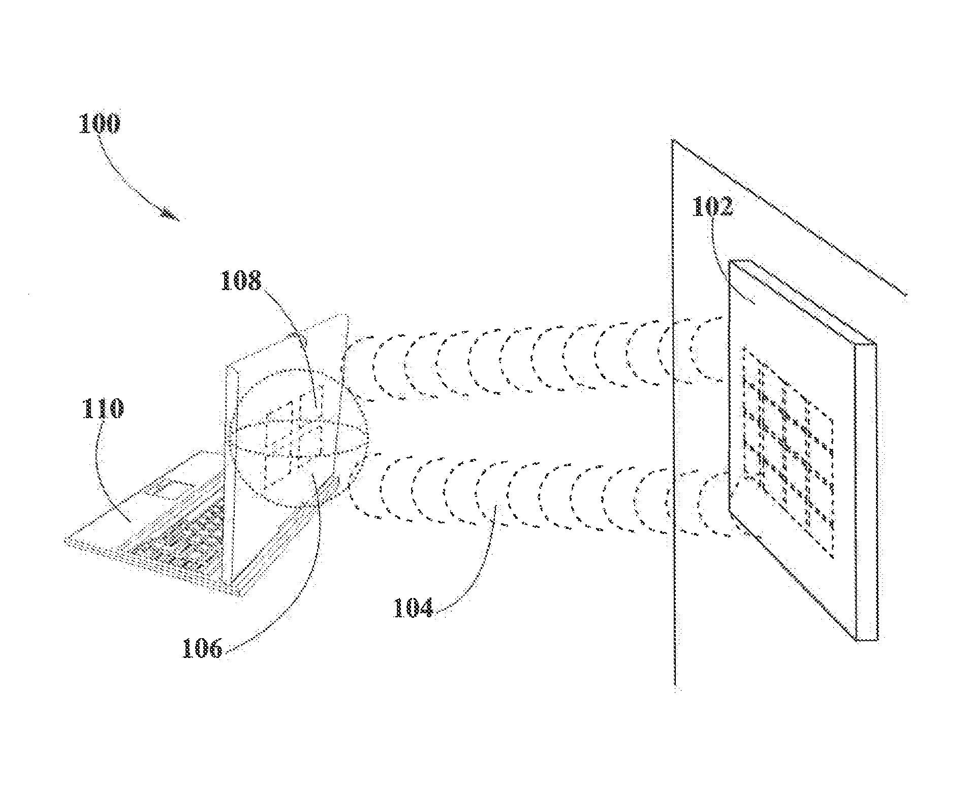
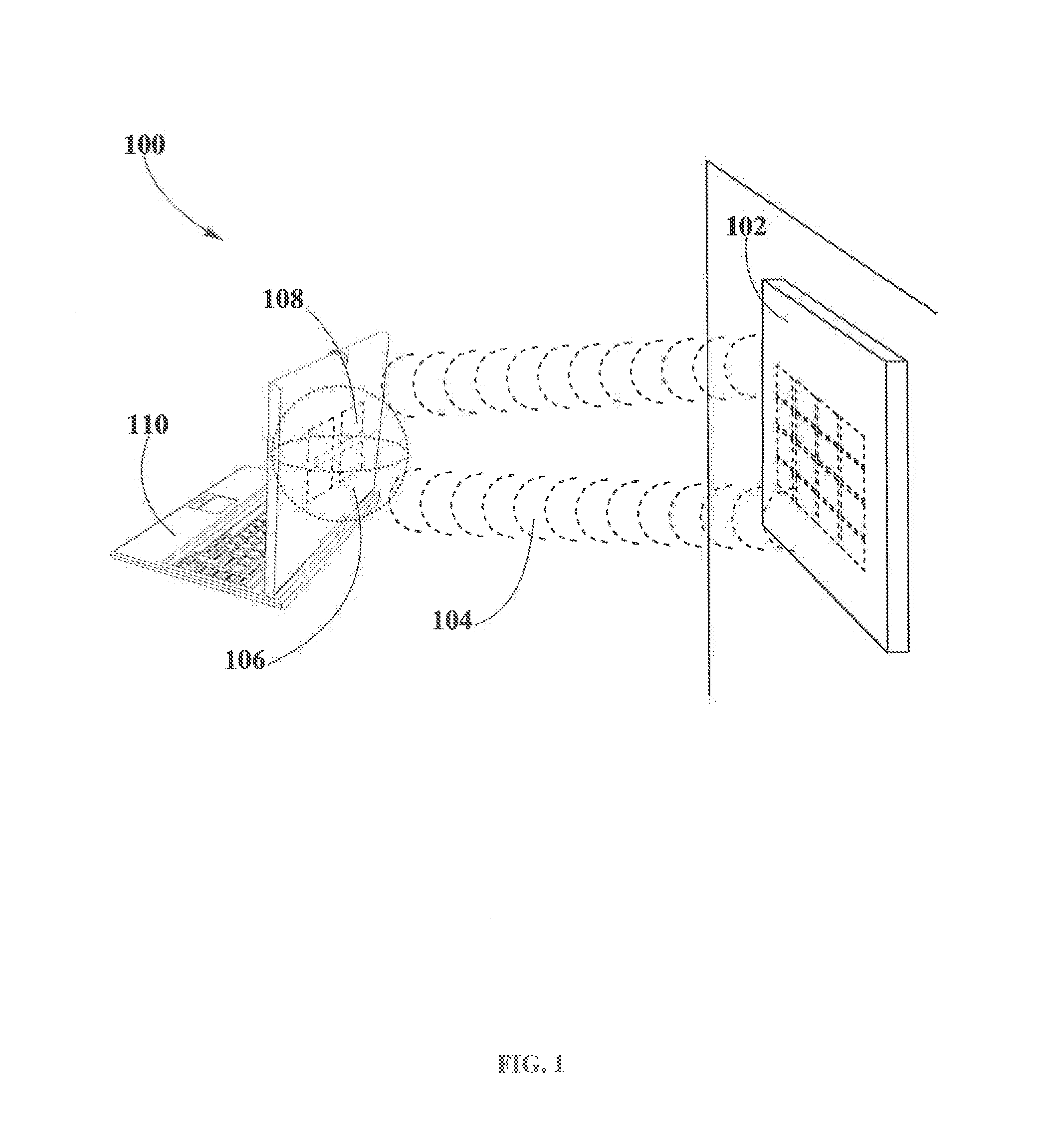
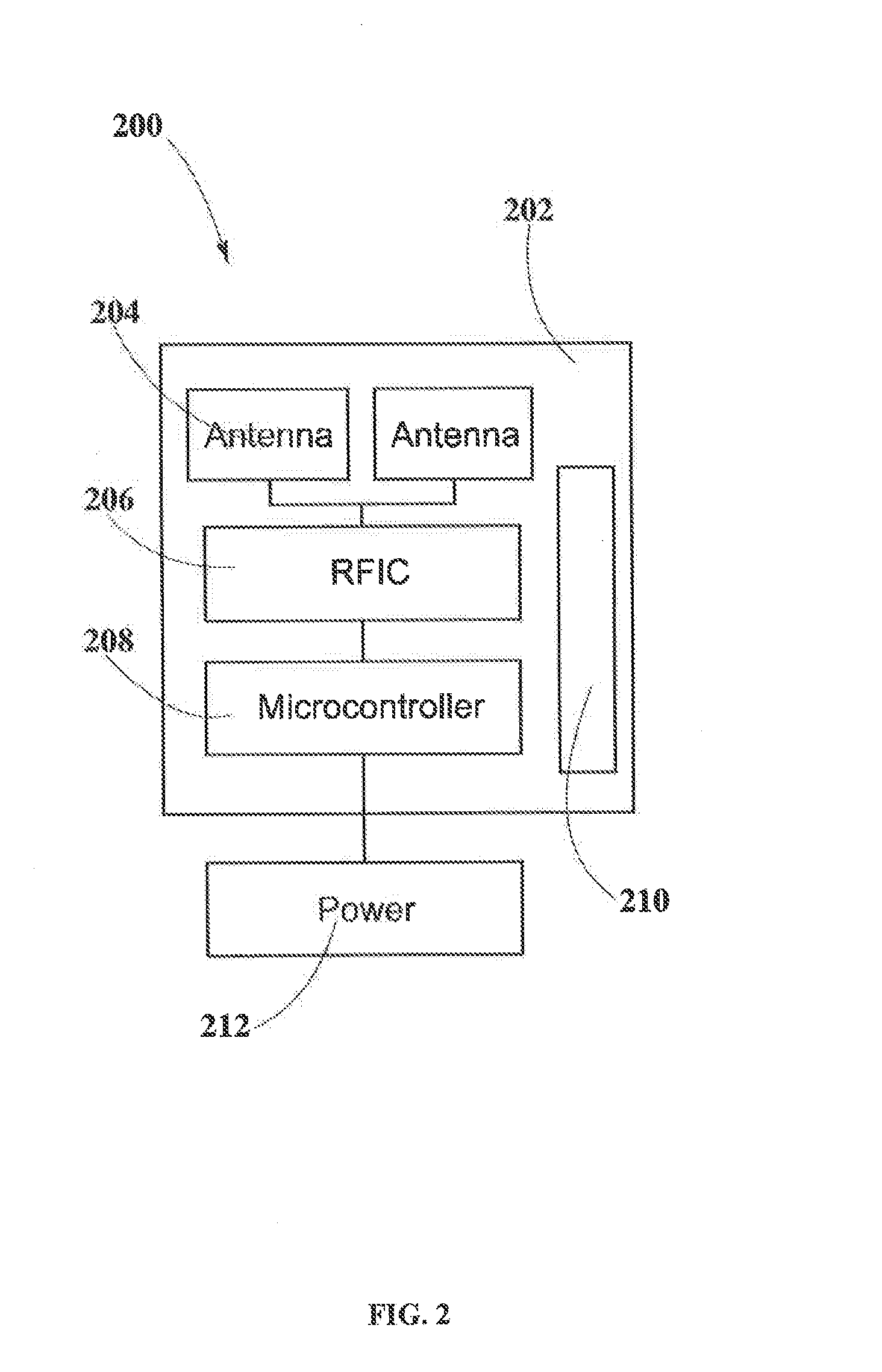
[0046]In example #1 a portable electronic heating jacket 700 that may operate at 7.4V may be powered or charged. In this example, a transmitter 200 may be used to deliver pockets of energy 106 onto heating jacket 700, in a process similar to the one depicted in FIG. 1. Transmitter 200 may have a single array of 8×8 of flat panel antennas where all the antenna elements 204 may operate in the same frequency band. Flat antennas may occupy less volume than other antennas, hence allowing a transmitter 200 to be located at small and thin spaces, such as, walls, mirrors, doors, ceilings and the like. In addition, flat panel antennas may be optimized for operating to long distances into narrow hall of wireless power transmission, such feature may allow operation of portable devices in long areas such as, train stations, bus stations, airports and the like. Furthermore, flat panel antennas of 8×8 may generate smaller pockets of energy 106 than other antennas since its smaller volume, this ma...


PUM


Abstract

The present disclosure may provide various electric receiver arrangements included in clothing pieces that require electric current to perform tasks, such as warming, cooling and displaying. Suitable wireless power transmission techniques, like pocket forming, may be used to provide the clothing pieces with wireless power. In some embodiments, receivers may include at least one antenna connected to at least one rectifier and one power converter. In other embodiments, receivers including a plurality of antennas, a plurality of rectifiers or a plurality of power converters may be provided. In addition, receivers may include communications components which may allow for communication to various electronic equipment including transmitters.

Description

CROSS-REFERENCES TO RELATED APPLICATIONS[0001]The present disclosure relates to U.S. non-provisional patent application Ser. No. 13 / 891,399, filed May 10, 2013, entitled “Receivers for Wireless Power Transmission”.FIELD OF INVENTION[0002]The present disclosure relates in general to receivers for wireless power transmission and more specifically to wireless power transmission receivers embedded in clothing and smart fabrics.BACKGROUND OF THE INVENTION[0003]Warming and cooling circuits embedded in clothing pieces may require power for performing their intended functions. Often, these devices include battery packs that last typically from a few hours to a couple of days. The constant use of these devices may require periodical charging. In some cases, such an activity may be tedious and may represent a burden to users. For example, a user may he required to carry chargers or additional batteries and may have to remember to plug in the device or the batteries for a suitable amount of ti...

Claims


Application Information

Patent Timeline
IPC IPC(8): H02J5/00A41D13/005A43B17/00H04W4/00A41D1/02A41B1/08H02J7/02A41D1/00A41D19/015H04W4/80
CPCH02J5/005A41D1/002A41D13/0051A43B17/003H04W4/008A41D1/02A41B1/08A41D13/0053H02J7/025A41D19/015H04W4/80H02J50/23H02J50/27H02J50/40H02J50/80H02J50/90H02J7/00034H02J50/20H02J50/005H04L9/40A41B11/006
Inventor LEABMAN, MICHAEL A.BREWER, GREGORY SCOTT
Owner ENERGOUS CORPORATION
Why Eureka
Try Eureka