
Waveform tracking device, ultrasound diagnostic device, and waveform tracking method

Inactive Publication Date: 2015-06-18
FURUNO ELECTRIC CO LTD
View PDF7 Cites 19 Cited by
  • Summary
  • Abstract
  • Description
  • Claims
  • Application Information

AI Technical Summary

Benefits of technology

The present invention provides a waveform tracking device and method that can accurately track the start point of a waveform and increase the speed of tracking processing. The device uses a determination index calculation step to determine the probability of a reflected wave from a measurement object, a tracking start point setting step to set the starting point for the waveform based on the determination index, and a tracking execution step to set tracking points for subsequent waves. This prevents the erroneous setting of the tracking start point, which results in more accurate waveform tracking.

Problems solved by technology

However, in setting the tracking start point in the configuration of Patent Literature 1, the tracking point cannot be found by calculating correlated values, and instead the technician has to perform the operation manually.
Therefore, not only does the measurement entail a great deal of time and work, but to a certain extent the measurement precision ends up being dependent on the skill of the technician, making it difficult to obtain consistent measurement results.
Furthermore, since the tracking in Patent Literature 1 is done by computing the correlation (similarity), the processing burden tends to be greater.

Method used


Image

  • Waveform tracking device, ultrasound diagnostic device, and waveform tracking method
  • Waveform tracking device, ultrasound diagnostic device, and waveform tracking method
  • Waveform tracking device, ultrasound diagnostic device, and waveform tracking method

Examples


Embodiment Construction

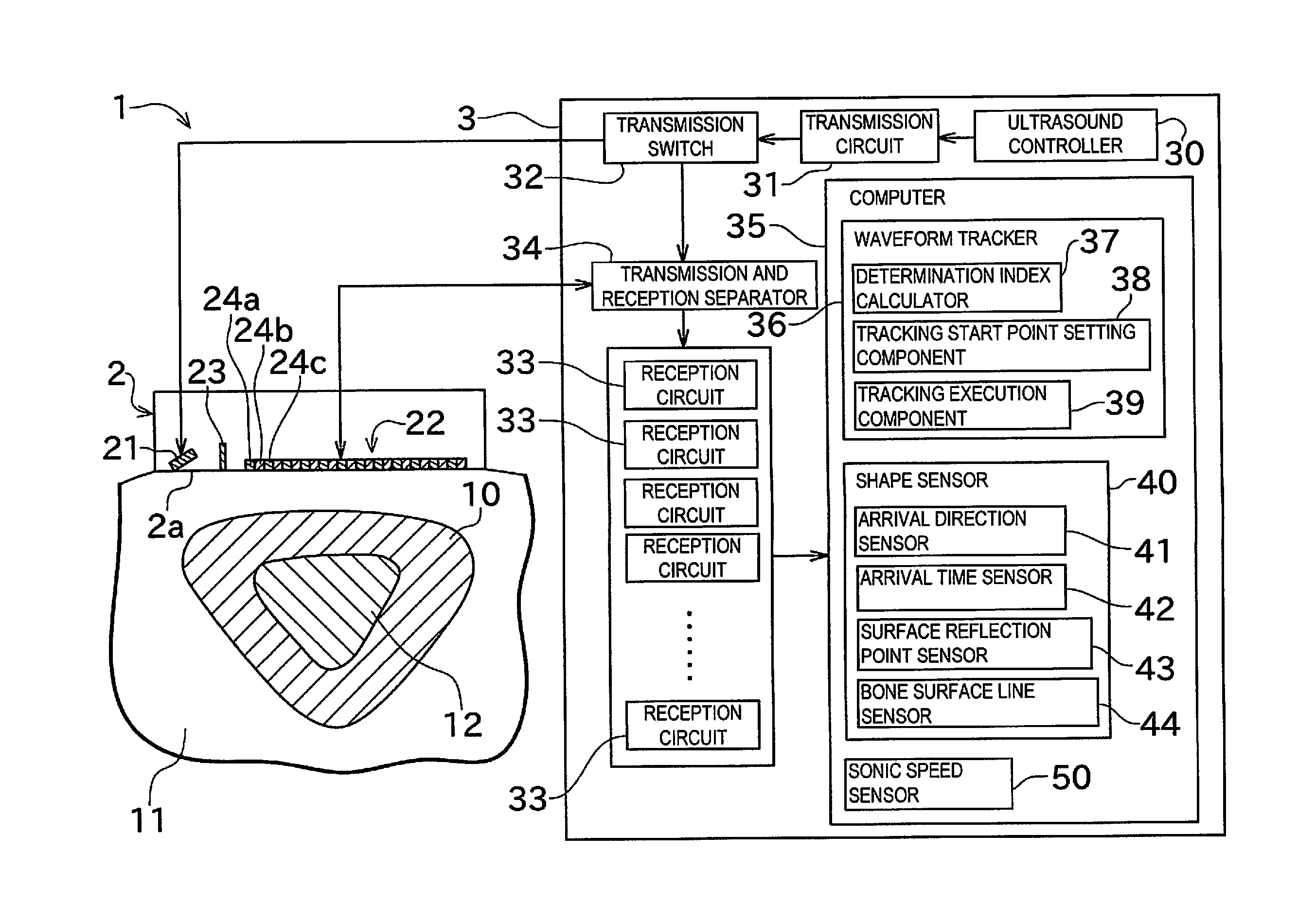
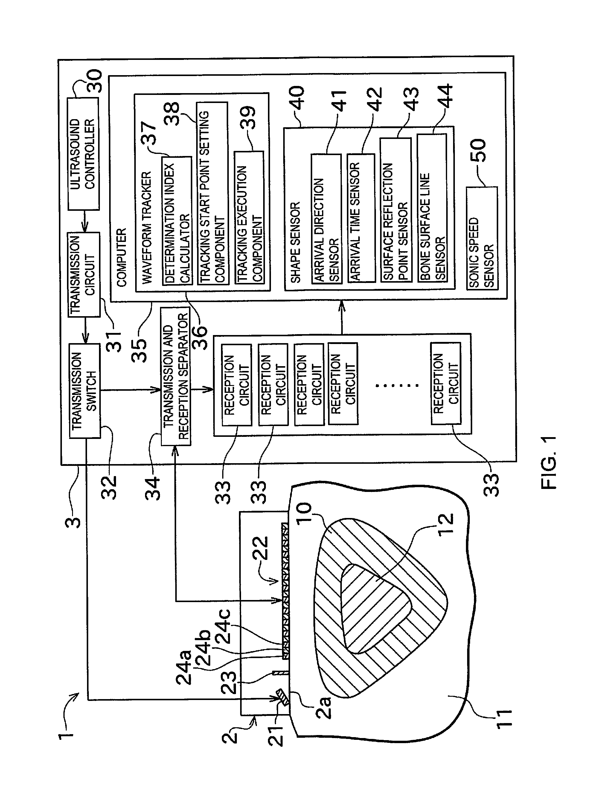
[0049]Embodiments of the invention will now be described through reference to the drawings. FIG. 1 is a simplified cross section and a function block diagram of a bone strength diagnostic device 1 pertaining to an embodiment of the present invention.

[0050]The bone strength diagnostic device (waveform tracking device, shape sensing device, sonic speed measurement device) 1 diagnoses, for example, the bone strength of cortical bone with a long tubular shape, such as a tibia (what is diagnosed is not, however, limited to this). More specifically, bone is generally made up of cortical bone 10 and spongy cancellous bone 12 that is present on the inside of the cortical bone 10. The outside of the cortical bone 10 is covered by soft tissue 11, such as muscle or fat. The bone strength diagnostic device 1 in this embodiment is configured so that ultrasonic waves are emitted from the outside of the soft tissue 11 toward the cortical bone 10, and the speed of sound through the cortical bone 10...


PUM


Abstract

A bone strength diagnostic device comprises oscillators, a determination index calculator, a tracking start point setting component, and a tracking execution component. A plurality of the oscillators are disposed in a line to acquire echo signals of a transmitted ultrasound beam. The determination index calculator calculates a determination index expressing a probability that the echo signal is a reflected wave from the surface of a cortical bone. The tracking start point setting component sets a tracking start point at a signal waveform timing corresponding to the echo signal for which the determination index satisfies a specific condition and that is received by one of the plurality of oscillators. The tracking execution component successively sets tracking points for the echo signals acquired from other oscillators using the tracking start point as an origin.

Description

CROSS REFERENCE TO RELATED APPLICATIONS[0001]This application is a U.S. National stage of International Application No. PCT / JP2013 / 066049 filed on Jun. 11, 2013. This application claims priority to Japanese Patent Application No. 2012-159557 filed on Jul. 18, 2012. The entire disclosure of Japanese Patent Application No. 2012-159557 is hereby incorporated herein by reference.BACKGROUND[0002]1. Field of the Invention[0003]The present invention relates mainly to a waveform tracking device that directs an ultrasound beam at a measurement object, acquires echo signals, and tracks the echo signals by utilizing the fact that there is continuity in the shape of the measurement object.[0004]2. Background Information[0005]A diagnostic device that makes use of ultrasound performs echo tracking processing to track a measurement object (such as blood vessel walls) on the basis of echo signals obtained from the ultrasound beam. Measuring a shape or position of a measurement object based on the r...

Claims


Application Information

Patent Timeline
IPC IPC(8): A61B8/08A61B8/14A61B8/00A61B5/00
CPCA61B8/0875A61B5/7264A61B8/145A61B8/4483A61B8/5223A61B5/7275A61B8/5207A61B8/0858G01S7/52036G01S15/8913G16H50/30
Inventor SUETOSHI, RYOICHICRETIN, DORIAN
Owner FURUNO ELECTRIC CO LTD
Learn More