
Illumination Device Comprising A Phosphor Arrangement And A Laser

a technology of illumination device and laser, which is applied in the direction of lighting and heating apparatus, light source combination, instruments, etc., can solve the problems of reducing the conversion efficiency of red phosphors compared with yellow and green phosphors, and imposing limits on the luminous flux and luminances that can be achieved with larp technology, so as to achieve improved luminous flux and high luminance

Inactive Publication Date: 2015-06-18
OSRAM GMBH
View PDF9 Cites 26 Cited by
  • Summary
  • Abstract
  • Description
  • Claims
  • Application Information

AI Technical Summary

Benefits of technology

The present invention is about a lighting device that uses LARP technology to achieve high luminous flux and high luminance for at least one light color. The device can use multiple laser radiations with different spectra to excite phosphors to produce colored light. The colored light can be mixed with further colored light to create mixed light with a desired color locus. The addition of a red laser diode can increase the luminous flux by about 10% compared to a configuration without it. This invention provides a more powerful and efficient lighting device for various applications.

Problems solved by technology

What is disadvantageous is that red phosphors have a lower conversion efficiency in comparison with yellow and green phosphors if they are irradiated with laser radiation having high surface power densities (e.g. 10-50 W / mm2).
As a result, for red light, in particular, limits are imposed on the luminous fluxes and luminances that can be achieved with LARP technology.

Method used


Image

  • Illumination Device Comprising A Phosphor Arrangement And A Laser
  • Illumination Device Comprising A Phosphor Arrangement And A Laser
  • Illumination Device Comprising A Phosphor Arrangement And A Laser

Examples


Embodiment Construction

[0034]Identical reference signs in different exemplary embodiments hereinafter denote features that are identical or of identical type.

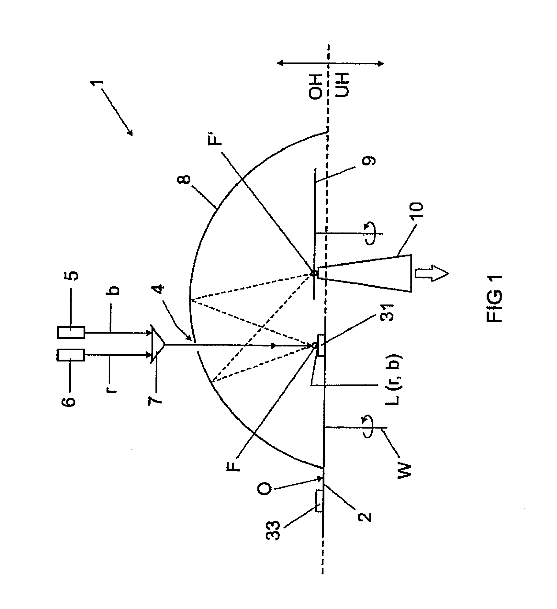
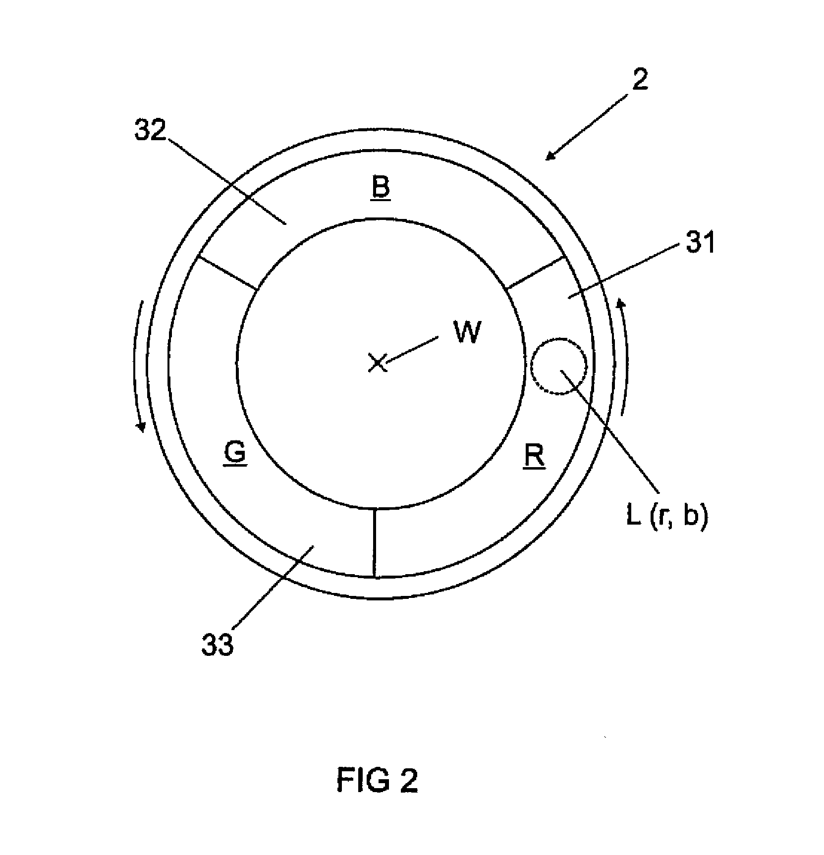
[0035]FIG. 1 shows, as a schematic sectional illustration in side view, a lighting device 1 comprising a phosphor wheel 2, which is rotatable about a rotation axis W, as indicated by the curved arrow. FIG. 2 shows in plan view one possible embodiment of the phosphor wheel 2. The lighting device 1 is suitable for example for application in a video projector with an image generating unit having the color channels red (r), green (g) and blue (b).

[0036]The phosphor wheel 2 comprises three luminous regions 31, 32 and 33 embodied as adjacent ring segments on a ring that is concentric with respect to the rotation axis W. The lighting device 1 furthermore comprises a first laser 5 for irradiating the three luminous regions 31 to 33 and also a second laser 6 for irradiating in each case only the luminous region 31 (R), which both irradiate a top side O of the...


PUM


Abstract

A lighting device comprising a phosphor arrangement (2) having a phosphor region; (31-33), a first laser (5) for irradiating a part of the phosphor region (31-33) with a first laser radiation; wherein the phosphor region (31-33) comprises at least one phosphor which can be irradiated by the first laser radiation and re-emits said first laser radiation at least partly in a manner wavelength-converted into colored light having a first light color; a second laser (6) configured for emitting a second laser radiation having a second light color, wherein the second light color of the second laser radiation is identical in color to the first light color of the wavelength-converted colored light; and wherein the lighting device is configured to simultaneously emit the second laser radiation and the wavelength-converted colored light of identical color emitted by the phosphor.

Description

TECHNICAL FIELD[0001]The invention relates to a lighting device comprising at least one laser and a phosphor arrangement that is irradiated by the laser radiation of the at least one laser. Furthermore, the invention relates to a method for operating said lighting device.[0002]The invention is applicable in particular to projection devices, for example for film and video projecting gear in industrial and medical image recognition, in technical and medical endoscopy, for lighting effects in the entertainment industry, for medical irradiations and in the automotive sector, in particular for headlights for motor vehicles.PRIOR ART[0003]Light sources having a high luminous flux and a high luminance are employed in a wide variety of fields, for instance in endoscopy and likewise in projection apparatuses, wherein gas discharge lamps are currently the most widely used for this purpose. In lighting applications, for example projection or endoscopy, on the basis of LARP (“Laser Activated Re...

Claims


Application Information

Patent Timeline
Patent Type & Authority Applications(United States)
IPC IPC(8): F21K99/00F21V7/00F21V9/40
CPCF21K9/56F21Y2113/005F21Y2101/025F21V7/0091F21K9/64G03B21/204G03B33/08G03B33/12F21Y2115/10F21Y2113/13F21Y2115/30F21Y2101/00F21S41/16F21V5/04F21V13/14F21V9/45F21V9/35F21V3/08F21V9/08F21V14/08G02B26/008
Inventor HOEHMANN, PETER
Owner OSRAM GMBH
Learn More