Apparatus and Method to Measure Display Quality

a technology of video display and display screen, applied in the field of measuring the quality of video display, can solve the problems of non-uniformity of illumination, appearance of “darkness”, and screen dirtying or damage, and achieve the effect of high average brightness

Inactive Publication Date: 2015-06-18
PROJECT GIANTS LLC
View PDF4 Cites 10 Cited by
  • Summary
  • Abstract
  • Description
  • Claims
  • Application Information

AI Technical Summary

Benefits of technology

[0008]A method for measuring a quality parameter, such as luminance uniformity, of a video display, according to some embodiments of the present invention, includes providing a plurality of pattern images to be displayed sequentially on the video display, measuring the amount of light produced by each pattern image using a wide-angle light sensor, and calculating the video display quality parameter using the measured light values corresponding to each displayed pattern. Each pattern used in accordance with this method is derived from an orthogonal matrix, resulting in each pattern having a high average brightness, thereby eliminating the need to use a narrow-angle, spot light meter, and instead allowing measurements to be made using a simple, wide-angle, incident-light or reflected-light photometer. This method is compliant with the relevant SMPTE measurement standard for measuring luminance uniformity. Additionally, some embodiments of the present invention provide an apparatus for practicing this method.

Problems solved by technology

Both the cinema screen itself and the video projection system can contribute to luminance non-uniformity.
Over time, a screen can become dirty or damaged, creating the appearance of “dark” or “light” spots on the screen.
Even on a clean and well-maintained screen, the distance of the projector from the screen and the type of lens used on the projector can cause areas of illumination non-uniformity.
Additionally, a cinema's ambient lighting may create areas of inconsistent screen illumination.
A spot light meter suitable to make such a measurement can be significantly expensive.
A high dynamic range would make the required wide-angle light meter more expensive.
Reducing the ambient light to an acceptable level could be impractical or inconvenient in many cases.
Furthermore, regardless of whether a spot light meter or a wide-angle meter is used, the measurement process described above requires at least 54 separate manual measurements (1 measurement per measurement zone times 9 zones per measurement location times 6 measurement locations), which can be tedious and prone to error.

Method used


Image

  • Apparatus and Method to Measure Display Quality
  • Apparatus and Method to Measure Display Quality
  • Apparatus and Method to Measure Display Quality

Examples


Embodiment Construction

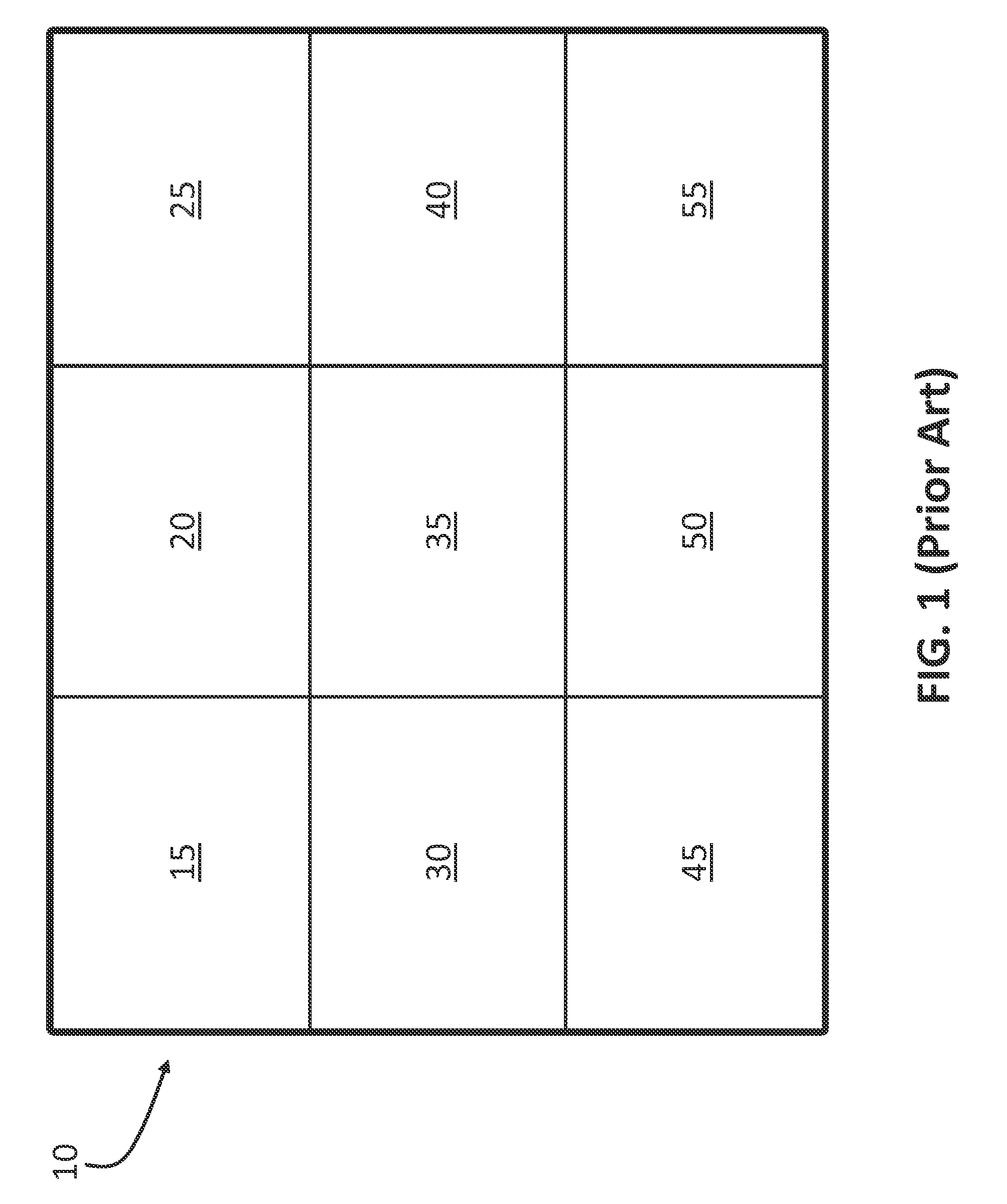
[0020]FIG. 1 shows a prior art video display screen 10 logically divided into nine equally sized rectangles (shown by thinner lines) that define the nine measurement zones required by the relevant SMPTE measurement standard. Each zone may be referred to by a name corresponding to the zone's row and column position on the screen, from the perspective of a person viewing the screen. For example, the four “corner” zones 15, 25, 45, and 55 may be referred to, respectively, as the “top-left,”“top-right,”“bottom-left,” and “bottom-right” zones. The four “edge” zones 20, 30, 40, and 50 may be referred to, respectively, as the “top-center,”“center-left,”“center-right,” and “bottom-center” zones. Zone 35 may be referred to as the “center” zone.

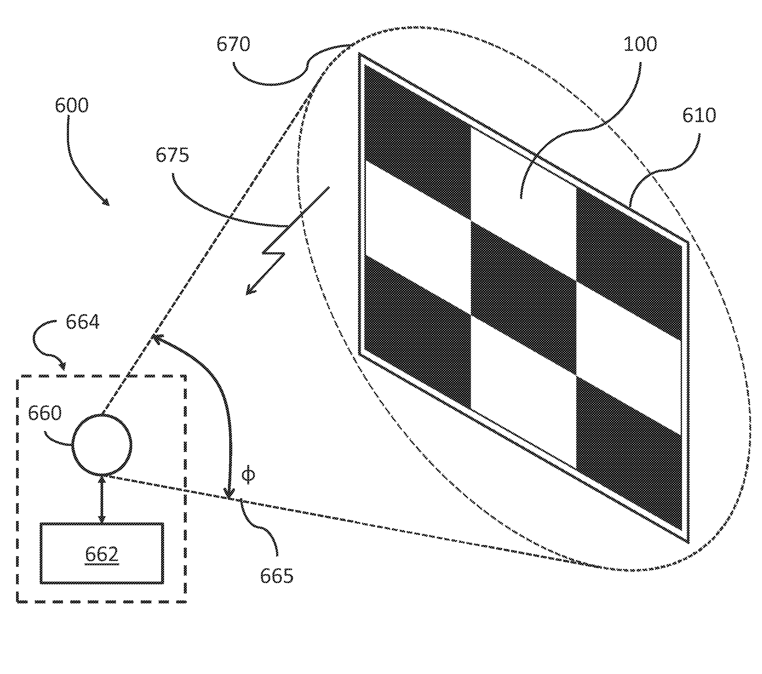
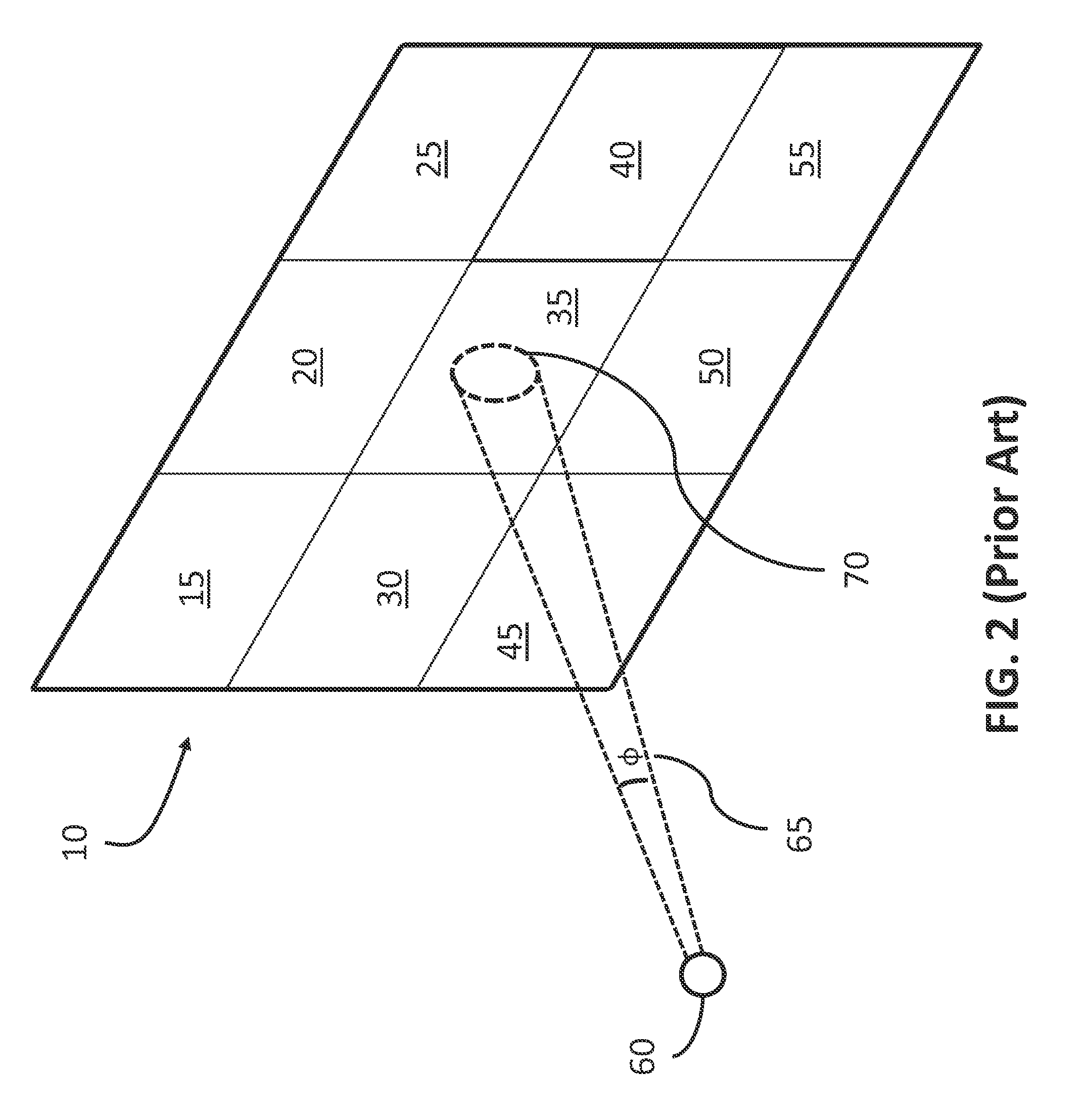
[0021]FIG. 2 shows a perspective view of a spot light meter 60 being used to measure luminance of the display 10 of FIG. 1 according to a conventional method. A full brightness (all white) image is displayed on the screen 10. From a selected viewing lo...


PUM

PropertyMeasurementUnit
luminanceaaaaaaaaaa
luminance uniformityaaaaaaaaaa
coloraaaaaaaaaa

Abstract

A method for measuring a quality parameter, such as luminance uniformity, of a video display, according to some embodiments of the present invention, includes providing a plurality of pattern images to be displayed sequentially on the video display, measuring the amount of light produced by each pattern image using a wide-angle light sensor, and calculating the video display quality parameter using the measured light values corresponding to each displayed pattern. Each pattern used in accordance with this method is derived from an orthogonal matrix, resulting in each pattern having a high average brightness, thereby eliminating the need to use a narrow-angle, spot light meter, and instead allowing measurements to be made using a simple, wide-angle, incident-light or reflected-light photometer. This method is compliant with the relevant SMPTE measurement standard for measuring luminance uniformity. Additionally, some embodiments of the present invention provide an apparatus for practicing this method.

Description

FIELD OF THE INVENTION[0001]The present invention relates to measuring the quality of video displays, and particularly to measuring a display's brightness or luminance uniformity.BACKGROUND OF THE INVENTION[0002]One important measure of the quality of a video display, including flat panel displays and cinema projection screens, is the uniformity of brightness, or luminance. With respect to cinema projection screens, in order to maintain an optimal viewing experience, cinema operators must periodically perform a measurement of the consistency of luminance across the screen in both the horizontal and vertical dimensions. Both the cinema screen itself and the video projection system can contribute to luminance non-uniformity. Over time, a screen can become dirty or damaged, creating the appearance of “dark” or “light” spots on the screen. These dirty or damaged spots can be colored so as to only affect certain colors of light, thereby creating a color-cast across the screen. Even on a ...

Claims


Application Information

Patent Timeline
Patent Type & Authority Applications(United States)
IPC IPC(8): G01N21/25G01J1/42
CPCG01N21/251G01J1/42G01N21/25H04N17/04H04N13/30H04N13/324H04N13/327
Inventor BAKER, DANIEL G.
Owner PROJECT GIANTS LLC
Why Eureka
Try Eureka