Universal remote radio unit bird armored fiber optic cable assembly

Inactive Publication Date: 2015-06-18
COMMSCOPE TECH LLC
View PDF9 Cites 34 Cited by
  • Summary
  • Abstract
  • Description
  • Claims
  • Application Information

AI Technical Summary

Problems solved by technology

However, large diameter cable sleeving may require elaborate and therefore expensive termination assemblies such as e

Method used


Image

  • Universal remote radio unit bird armored fiber optic cable assembly
  • Universal remote radio unit bird armored fiber optic cable assembly
  • Universal remote radio unit bird armored fiber optic cable assembly

Examples


Embodiment Construction

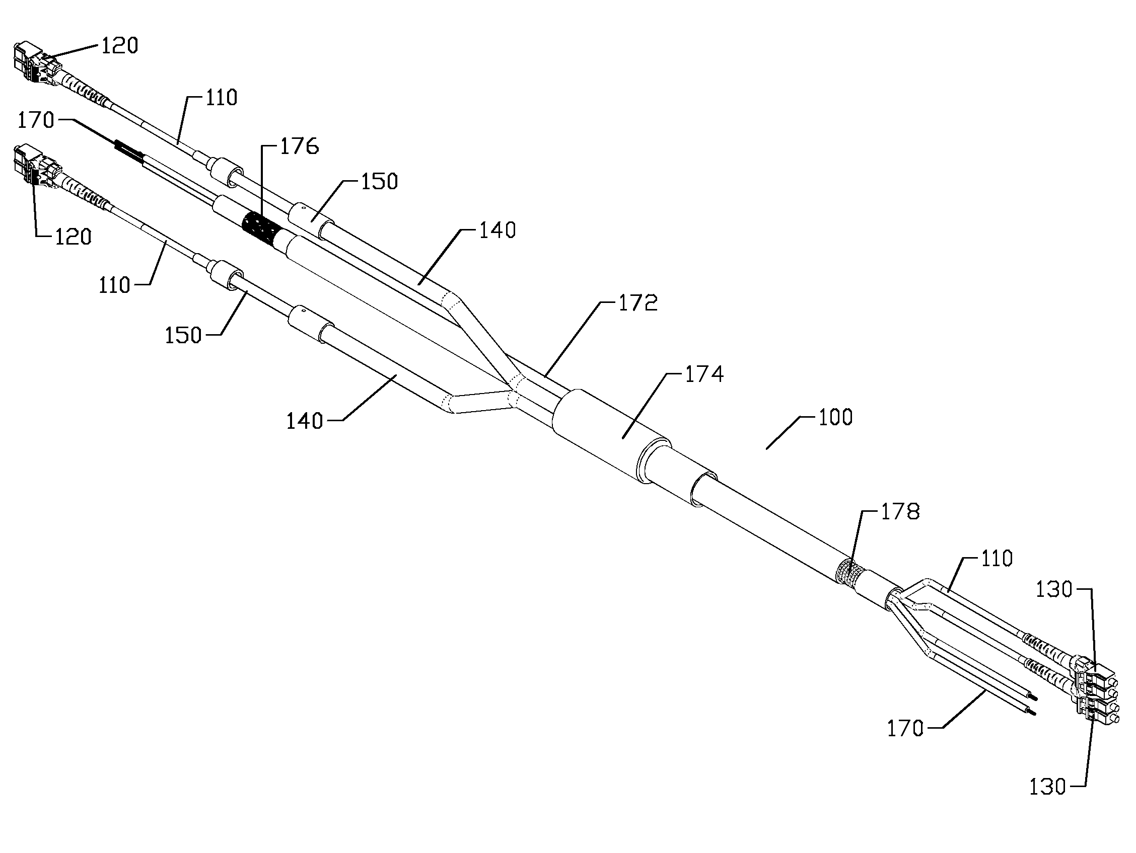
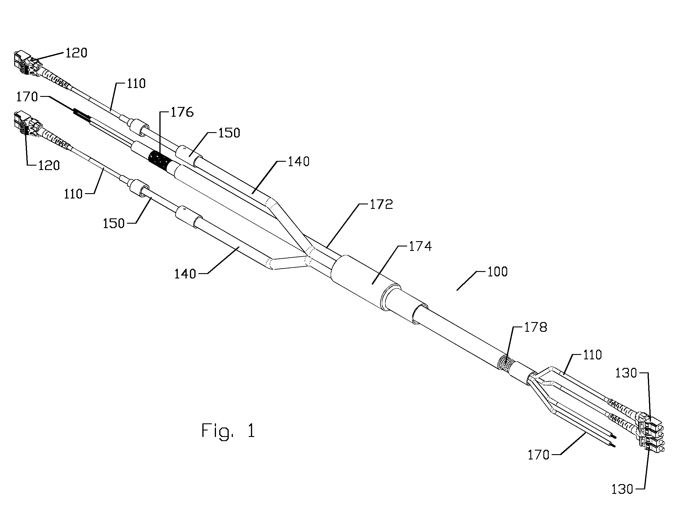
[0035]The inventor has recognized that it is time consuming, hazardous and expensive to install new cable assemblies on a tall radio tower. A single user may utilize different types of RRU / RRH. To avoid duplication of incompatible assemblies and simplify sourcing for the user, a single solution that can be used with multiple types of RRU / RRH has been devised. Thereby, should the rapidly evolving RRU / RRH technology adopt one or the other interconnection / sealing interfaces as a standard and / or the user select the alternative RRU / RRH in the future, the RRU / RRH may be easily exchanged in the future without also requiring exchange of the entire cable assembly.

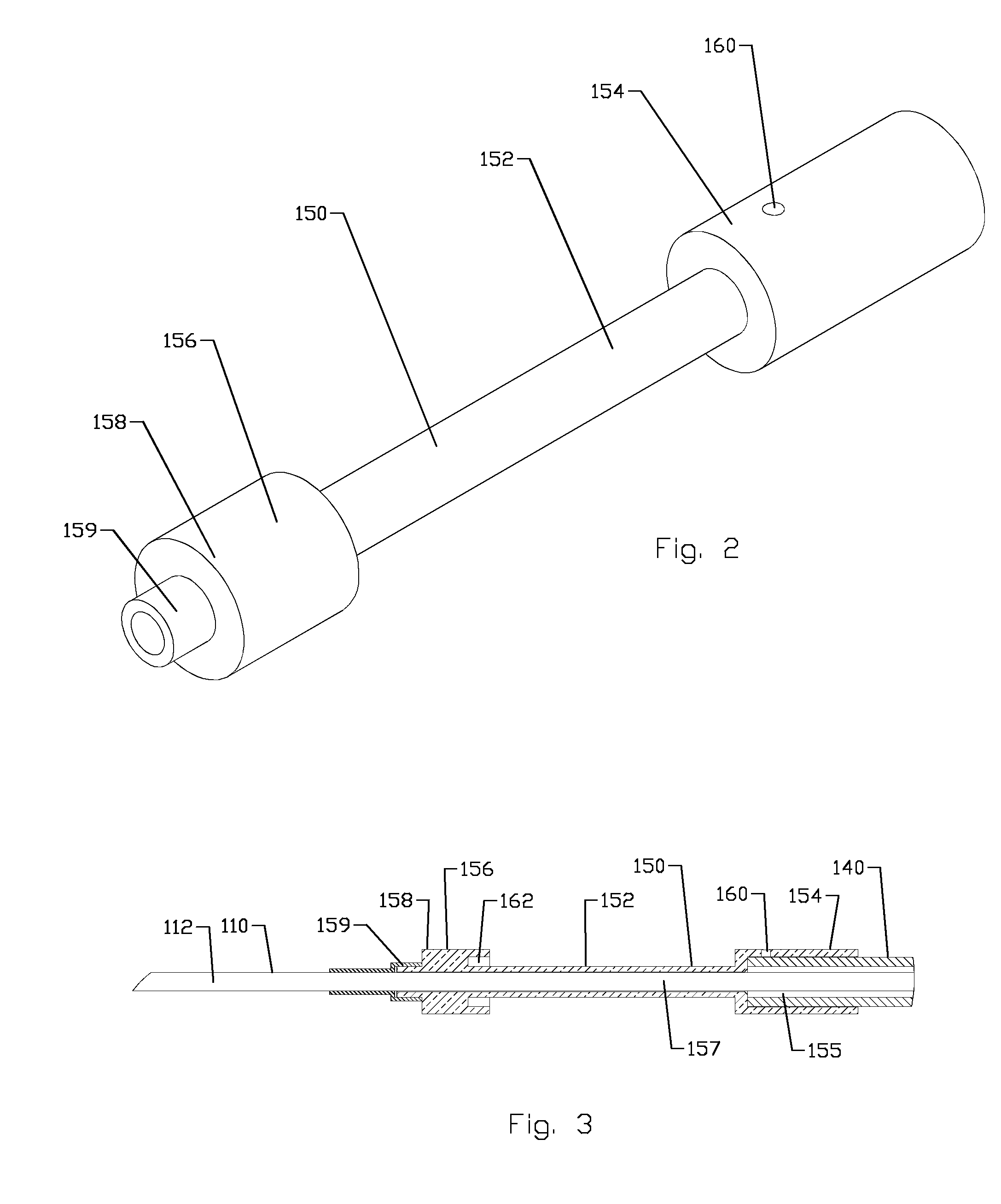
[0036]These cable assemblies may include adapter sleeves which include a plurality of differently dimensioned outer diameter surfaces and other features, to allow the same cable assembly to be used with a variety of different RRU / RRHs, despite the differences in connection mechanisms on these various different RRU / RRHs.

[0037]A fiber...


PUM

PropertyMeasurementUnit
Lengthaaaaaaaaaa
Lengthaaaaaaaaaa
Diameteraaaaaaaaaa

Abstract

A fiber optic cable has a cable core that includes at least one optical fiber coupled to a fiber optic connector. A cable adapter sleeve is axially mounted on the cable core to surround the cable core, the cable adapter sleeve including a body portion that has a first outer diameter and a collar that has a second outer diameter that is greater than the first outer diameter. A crush sleeve is seated within a crush groove of the collar.

Description

BACKGROUND[0001]1. Field of the Invention[0002]This invention relates to fiber optic and hybrid electro-optical cable assemblies. More particularly, the invention relates to cable assemblies adaptable to a variety of different remote radio unit conductor entry dimensional specifications.[0003]2. Description of Related Art[0004]The wireless communications industry is changing from traditional signal delivery from ground based transceivers delivering / receiving the RF signal to / from the antenna atop the radio tower via bulky / heavy / high material cost semi-rigid metal RF coaxial cable to optical signal delivery to a tower top mounted transceiver known as a remote radio unit (RRU) or remote radio head (RRH) with implementation of fiber to the antenna (FTTA) cabling.[0005]As this area of the market is evolving quickly, many original equipment manufacturers (OEM) are providing different RRU / RRH with different termination requirements, requiring different fiber optic cable assemblies with di...

Claims


Application Information

Patent Timeline
IPC IPC(8): G02B6/38G02B6/46G02B6/44
CPCG02B6/3887G02B6/46G02B6/4416G02B6/443G02B6/4429G02B6/4471G02B6/4472Y10T29/49174Y10T29/49826
Inventor ISLAM, NAHID
Owner COMMSCOPE TECH LLC
Why Eureka
Try Eureka