Phase locked loop (PLL) apparatus and operating method of pll apparatus

a phase lock and loop technology, applied in the direction of electrical equipment, pulse automatic control, etc., can solve the problems of increasing relevant costs and difficult overall improvement of phase noise, and achieve the effects of improving phase noise, reducing the output frequency of the vco, and reducing the frequency division ratio of the frequency divider

Inactive Publication Date: 2015-06-18
ELECTRONICS & TELECOMM RES INST
View PDF4 Cites 6 Cited by
  • Summary
  • Abstract
  • Description
  • Claims
  • Application Information

AI Technical Summary

Benefits of technology

[0014]An aspect of the present invention provides a phase locked loop (PLL) apparatus that may down-convert a frequency of a signal oscillated by a voltage-controlled oscillator (VCO) using a fixed frequency signal provided by a PLL unit, and provide the down-converted signal to a phase comparator, thereby decreasing an output frequency of the VCO, decreasing a frequency division ratio of a frequency divider having an effect on phase noise, and improving the phase noise.
[0015]Another aspect of the present invention also provides an effective improvement of overall phase noise of a PLL apparatus using a fixed frequency signal by maximizing a bandwidth associated with a loop filter in a PLL unit, minimizing a reference frequency of a phase comparator in the PLL unit, and improving the phase noise with respect to the fixed frequency signal provided by the PLL unit, without use of a multiplier and a high-priced oscillator, for example, a temperature compensated crystal oscillator (TCXO).

Problems solved by technology

However, since phase noise of a fixed local oscillator (LO) in the offset PLL may be output within the loop filter band, an overall improvement of phase noise may be difficult.
However, due to use of a multiplier and a high-frequency oscillator, for example, the TCXO, relevant costs may increase.

Method used


Image

  • Phase locked loop (PLL) apparatus and operating method of pll apparatus
  • Phase locked loop (PLL) apparatus and operating method of pll apparatus
  • Phase locked loop (PLL) apparatus and operating method of pll apparatus

Examples


Embodiment Construction

[0025]Reference will now be made in detail to exemplary embodiments of the present invention, examples of which are illustrated in the accompanying drawings, wherein like reference numerals refer to the like elements throughout. Exemplary embodiments are described below to explain the present invention by referring to the figures.

[0026]Hereinafter, a phase locked loop (PLL) apparatus and an operating method of the PLL apparatus will be described in detail with reference to the accompanying drawings. Herein, the PLL apparatus may be provided in a form of an offset PLL.

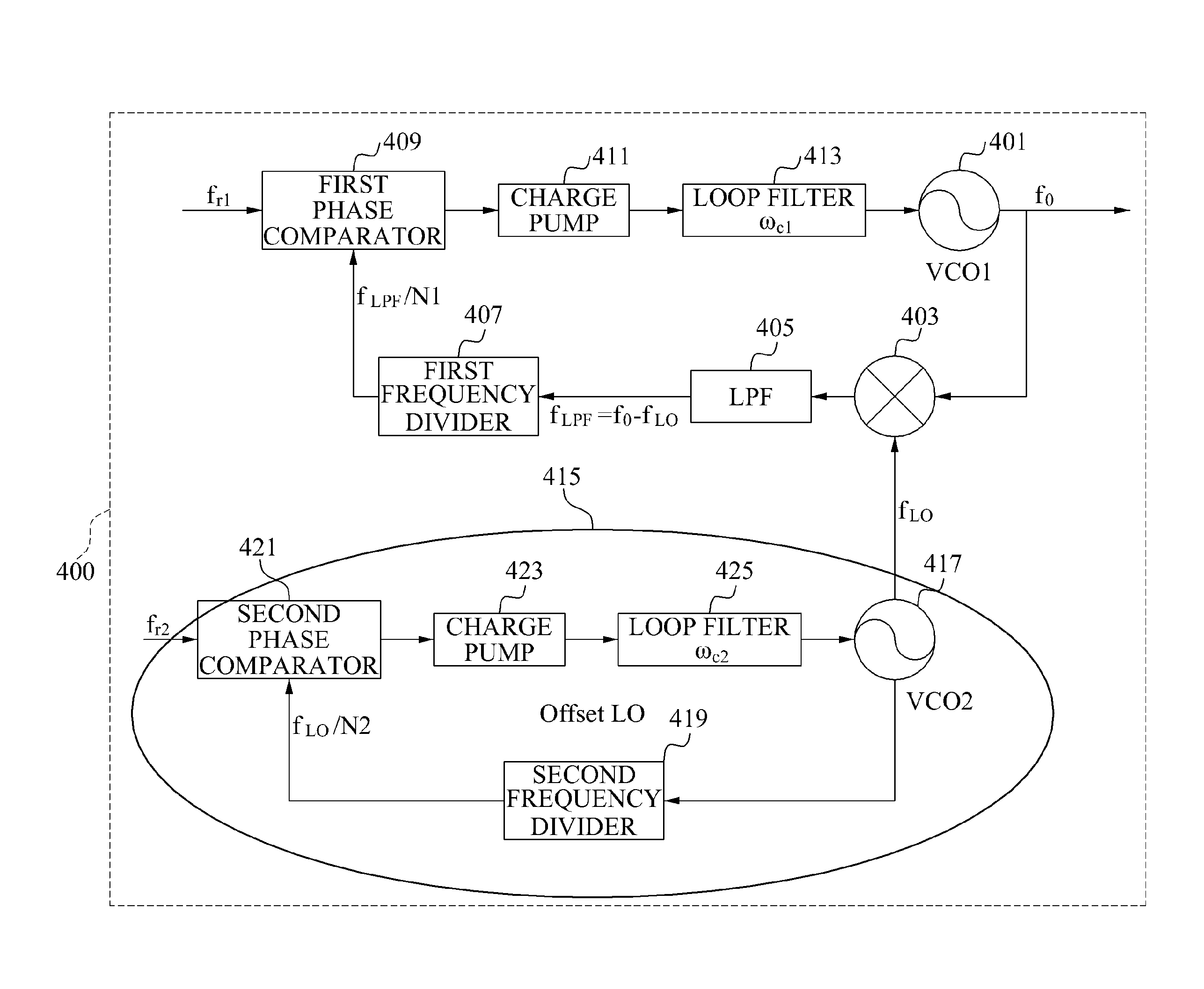
[0027]FIG. 4 is a diagram illustrating a configuration of a PLL apparatus 400 according to an embodiment of the present invention.

[0028]Referring to FIG. 4, the PLL apparatus 400 may include a first voltage-controlled oscillator (VCO) 401, a converter 403, a low-pass filter (LPF) 405, a first frequency divider 407, a first phase comparator 409, a charge pump 411, a loop filter 413, and a PLL unit 415.

[0029]The first VCO...


PUM


Abstract

Provided are a phase locked loop (PLL) apparatus and an operating method of the PLL apparatus including a PLL unit to provide a fixed frequency signal, a converter to convert, using the fixed frequency signal, a frequency of a first signal oscillated by a first voltage-controlled oscillator (VCO) based on a first control voltage, a first frequency divider to divide the converted frequency of the first signal, and a first phase comparator to compare the divided frequency of the first signal to an input first reference frequency and detect a first phase difference, wherein the first VCO may adjust the first control voltage based on the detected first phase difference to equalize the divided frequency of the first signal to the first reference frequency.

Description

CROSS-REFERENCE TO RELATED APPLICATION[0001]This application claims the benefit of Korean Patent Application No. 10-2013-0155536, filed on Dec. 13, 2013, in the Korean Intellectual Property Office, the disclosure of which is incorporated herein by reference.BACKGROUND[0002]1. Field of the Invention[0003]The present invention relates to a low-priced phase locked loop (PLL) apparatus with improved phase noise.[0004]2. Description of the Related Art[0005]Similar to a satellite communication system, a terminal may require a phase locked loop (PLL) apparatus capable of generating a local oscillation signal of a wide frequency band to transmit a signal at a predetermined frequency assigned from a central station in a wide frequency band.[0006]The PLL apparatus may generate the local oscillation signal of the wide frequency band using a voltage-controlled oscillator (VCO).[0007]FIG. 1 is a diagram illustrating a configuration of a general PLL apparatus.[0008]Referring to FIG. 1, the genera...

Claims


Application Information

Patent Timeline
Patent Type & Authority Applications(United States)
IPC IPC(8): H03L7/099H03L7/087H03L7/093
CPCH03L7/099H03L7/087H03L7/093H03L7/185H03L7/23
Inventor RYU, JOON GYU
Owner ELECTRONICS & TELECOMM RES INST
Why Eureka
Try Eureka