Network device and network system
a network device and network technology, applied in the field of network devices and network systems, can solve the problems of individual sender network devices incurring significant costs for such measures, and the inability to ensure the protection against attacks, so as to achieve the effect of detecting attacks and ensuring the protection against attacks
- Summary
- Abstract
- Description
- Claims
- Application Information
AI Technical Summary
Benefits of technology
Problems solved by technology
Method used
Image
Examples
first embodiment
Configuration of Network System
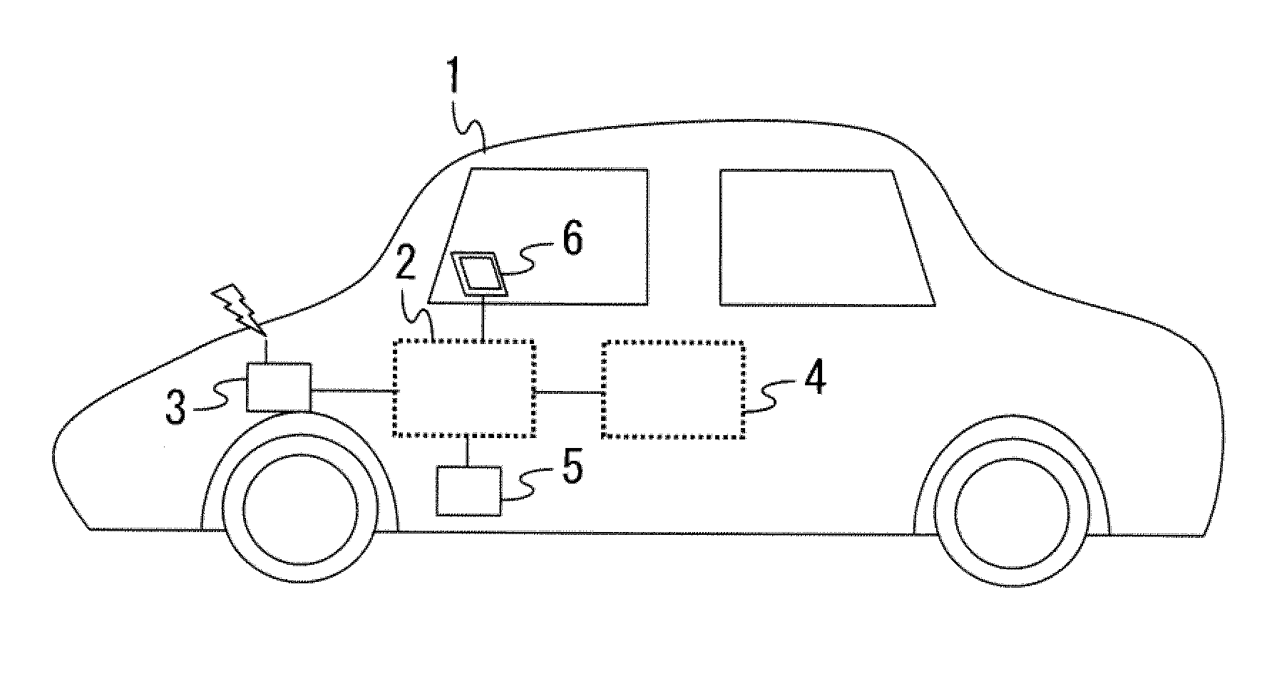
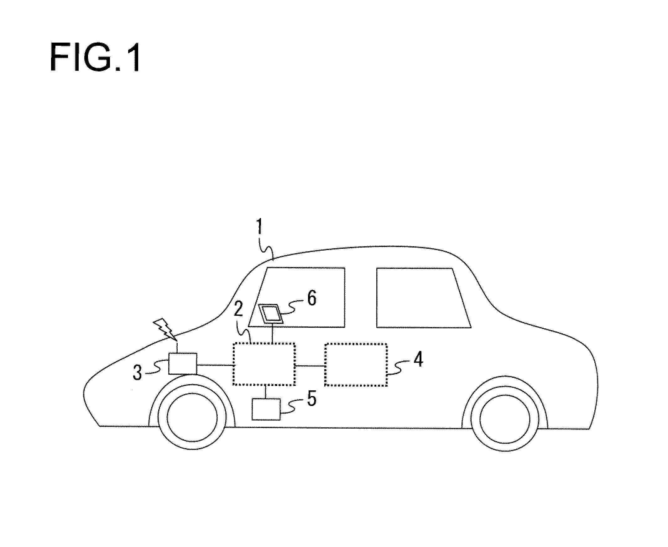
[0027]FIG. 1 presents an example of a network system that includes network devices, as achieved in the first embodiment of the present invention. FIG. 1 shows a control system 1 that includes a network system 2 installed in a mobile body such as an automobile. The network system 2 in FIG. 1 is configured with, for instance, an onboard network (CAN: Controller Area Network, CANFD: CAN with Flexible Data-rate, Ethernet (registered trademark) or the like). FIG. 1 shows a wireless communication unit 3 engaged in wireless communication (e.g., mobile telephone communication or protocol-based communication such as wireless LAN or WAN) with a device outside the control system 1, and a network system 4 that adopts a protocol different from that in the network system 2 or a protocol matching that in the network system 2. FIG. 1 shows a wired communication unit 5, which includes, for instance, a diagnostics terminal (OBD), an Ethernet terminal and an external rec...
second embodiment
[0144]An example in which the network device that engages in authentication processing invalidates all transfer data with data formats that do not match expected formats, as well as the invalidation to transfer data having failed authentication, at the time of transfer data detection, will be described next. In reference to FIG. 16, the processing executed in the control unit 501 of the network device achieved in the embodiment at the time of transfer data detection will be explained. The processing differs from that executed in the first embodiment in that it includes an additional step, i.e., step S201, in which data format decision-making processing is executed. Accordingly, an explanation will be given in reference to FIG. 16 by focusing on the difference from the first embodiment, without providing a repeated explanation of the processing executed in steps assigned with the same step numbers as those in FIG. 15.
[0145]The term “data format” in this context refers to a format tha...
third embodiment
[0152]Next, an example in which data are invalidated as a GW 303 or an SW 304 relays data being transferred from one network link 301 to another network link 301 will be described. While the following explanation is given by assuming that the network device achieved in the embodiment is a GW 303 the present invention may be adopted in a similar manner in an SW 304.
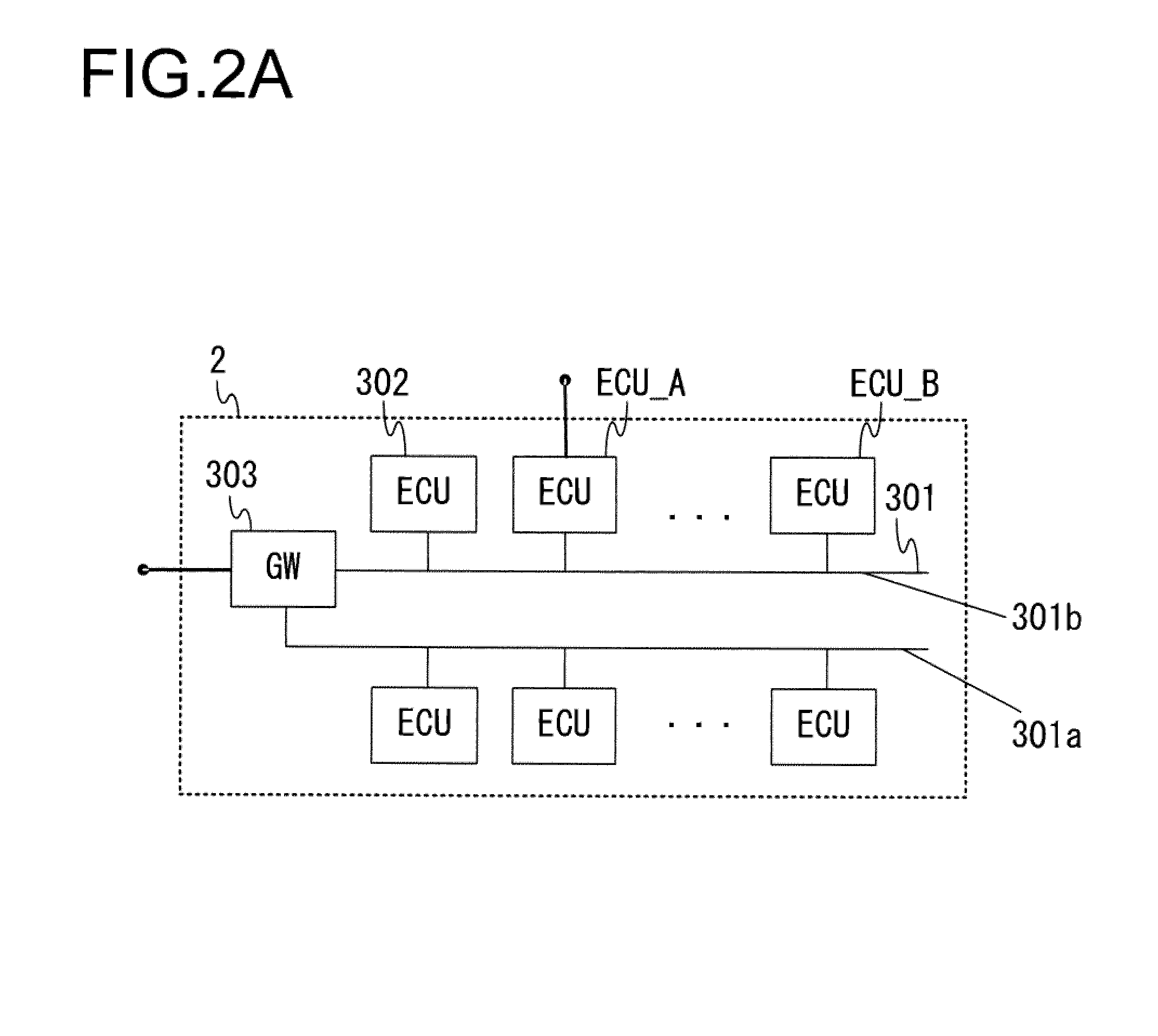
[0153]The GW 303 may relay data transferred from the network link 301a to which the sender network device is connected, to the network link 301b, different from the network link 301a, to which the recipient network device is connected, as illustrated in FIG. 2A. In this situation, the GW 303 takes in the data input thereto from the network link 301a to which the sender network device is connected, verifies the recipient based upon the data header, and outputs the data to the network link 301b. Since the data are transferred with low latency, the communication interface 402 or the control unit 501 in the GW 303 analyzes the...
PUM
 Abstract
Description
Claims
Application Information
 - R&D
- Intellectual Property
- Life Sciences
- Materials
- Tech Scout
- Unparalleled Data Quality
- Higher Quality Content
- 60% Fewer Hallucinations
Browse by: Latest US Patents, China's latest patents, Technical Efficacy Thesaurus, Application Domain, Technology Topic, Popular Technical Reports.
© 2025 PatSnap. All rights reserved.Legal|Privacy policy|Modern Slavery Act Transparency Statement|Sitemap|About US| Contact US: help@patsnap.com


