
Image shake correcting apparatus and control method therefor, optical apparatus, and image pickup apparatus

Active Publication Date: 2015-06-18
CANON KK
View PDF8 Cites 9 Cited by
  • Summary
  • Abstract
  • Description
  • Claims
  • Application Information

AI Technical Summary

Benefits of technology

The invention provides an image shake correcting apparatus that can successfully correct image shake even when the apparatus is subject to a large shake. The apparatus can improve image shake correction even when it has been previously shaken.

Problems solved by technology

Alternatively, an image-swing (swing-back) can occur after the panning operation or the like to cause the user to feel discomfort about the operation of the camera or the image.
However, the technique described in Japanese Patent Laid-Open No. 2006-113264 has a weak effect on the image shake correction immediately after the panning operation or the like.
Also, in the technique described in Japanese Patent Laid-Open No. 2011-118073, because the operation in which the position of the correcting lens is centered by position control, when exposure is not being performed, the effect of the image shake correction on the low-pass components of the shake detection signal such as a swing of the user's body is weakened.
Also, if the offsets of the angular velocity sensor and the temperature fluctuation are large, and the shake at a low-frequency is relatively large during photographing while walking or the like, the position of the correcting lens deviates from the center of the movable range since this technique does not use the HPF.
If a crystal gyro sensor or the like with a small offset and the temperature fluctuation is used, the cost may increase.
Also, the technique described in Japanese Patent Laid-Open No. 2010-004370 reduces the performance of the image shake correction for the low-frequency during the exposure if the electronic image shake correction cannot be performed.

Method used


Image

  • Image shake correcting apparatus and control method therefor, optical apparatus, and image pickup apparatus
  • Image shake correcting apparatus and control method therefor, optical apparatus, and image pickup apparatus
  • Image shake correcting apparatus and control method therefor, optical apparatus, and image pickup apparatus

Examples


Embodiment Construction

[0024]Hereinafter, preferred embodiments of the present invention will be described with reference to the drawings. The present invention can be applied to an interchangeable lens mounted on a digital single-lens reflex camera, an optical apparatus such as a lens barrel, an image pickup apparatus such as a digital video camera, a monitoring camera, a Web camera, or the like, and electronic equipment including an image pickup apparatus, such as a mobile phone, a tablet terminal, or the like. Note that this invention does not intend to be limited to the following embodiments, and illustrates only a concrete example that has some advantages in the practice of this invention. Also, all the combinations of the characteristics described in the following embodiments are not always essential for the present invention.

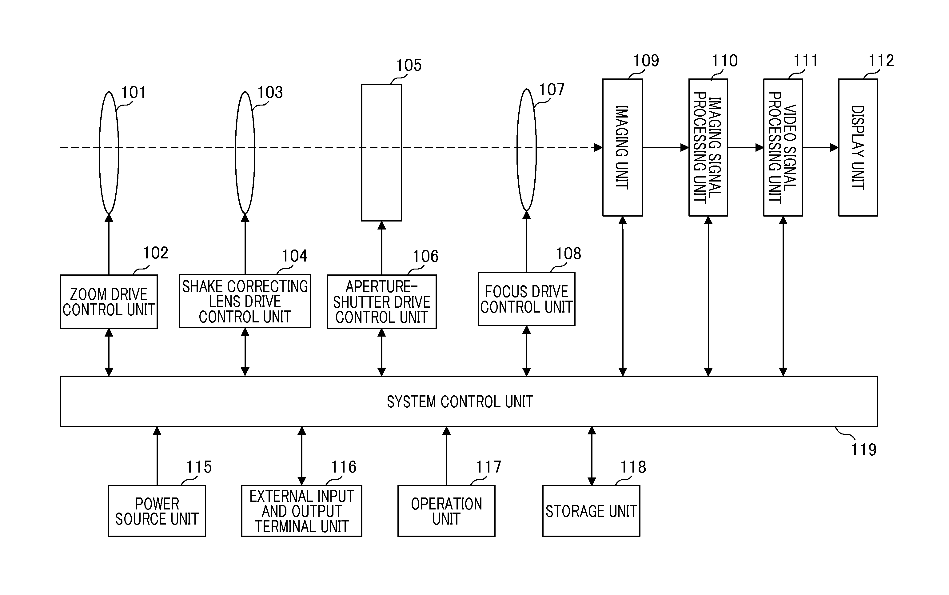
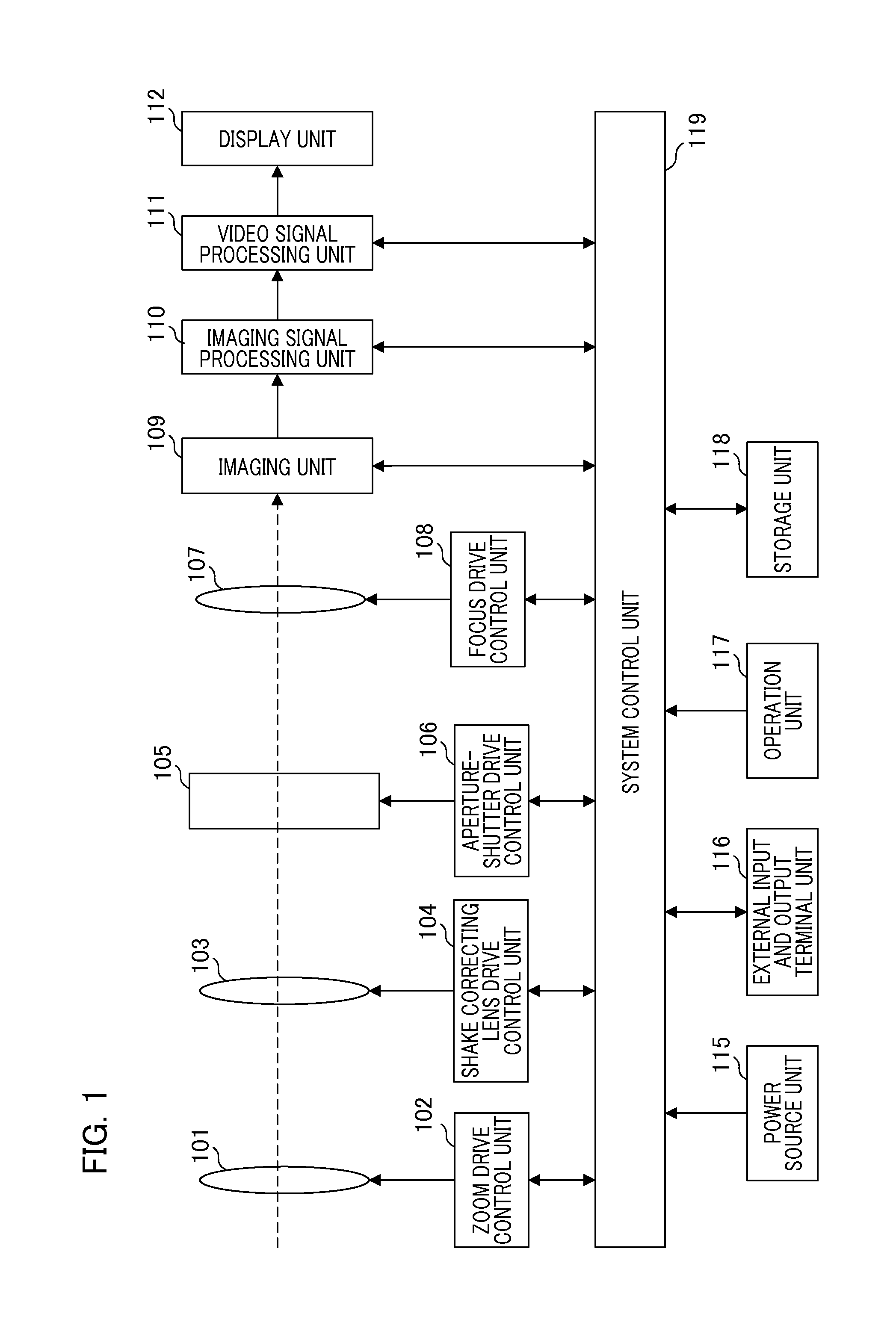
[0025]FIG. 1 is a block diagram illustrating an example of a functional configuration of an image pickup apparatus according to an embodiment of the present invention. Although...


PUM


Abstract

This image pickup apparatus detects a shake and performs feedback control. A LPF and a subtracting unit divide a detection signal into low-frequency components and high-frequency components. An output of the LPF for integrating the high-frequency components and the LPF for integrating the low-frequency components are combined in an adding unit to output the result as the target position of the correcting lens. A HPF removes the low-pass components of the shake amount applied to the image pickup apparatus. A control switching determination unit switches a first control mode for performing an image shake correction by a signal produced by frequency dividing a signal after processing signal with the HPF, and a second control mode for performing the image shake correction by a signal that is generated by subtracting a fixed offset amount calculated with the HPF based on the shake signal and dividing the result into the frequency components.

Description

BACKGROUND OF THE INVENTION[0001]1. Field of the Invention[0002]The present invention relates to a technique for correcting an image shake in an optical apparatus, an image pickup apparatus or the like.[0003]2. Description of the Related Art[0004]An image shake can be caused on an image captured by an image pickup apparatus such as a digital camera by a shaking of a user's hand which holds a camera main body when capturing the image. Therefore, there have been some apparatuses with a function for detecting vibration applied to the camera main body to correct the image shake of an object image. In this technique, optical image shake correction processing and electronic image shake correction processing are known. The optical image shake correction processing detects a shake of a camera main body with an angular velocity sensor or the like to move an optical member in a photographing optical system (a correcting lens) to change a direction of an optical axis in the photographing optic...

Claims


Application Information

Patent Timeline
IPC IPC(8): H04N5/232G02B27/64
CPCH04N5/23264H04N5/23258H04N5/23261G02B27/646G02B7/102H04N23/6815H04N23/6812H04N23/687
Inventor TAKEUCHI, KENJI
Owner CANON KK
Learn More