
Apparatus for copying a hologram

a technology of holograms and apparatuses, applied in the field of holograms, can solve the problems of difficult to achieve the appropriate level of overmodulation, the relative intensities of diffracted and zero orders cannot be controlled to better than 5%, and the interference to form the desired grating structur

Inactive Publication Date: 2015-06-25
DIGILENS
View PDF3 Cites 71 Cited by
  • Summary
  • Abstract
  • Description
  • Claims
  • Application Information

AI Technical Summary

Benefits of technology

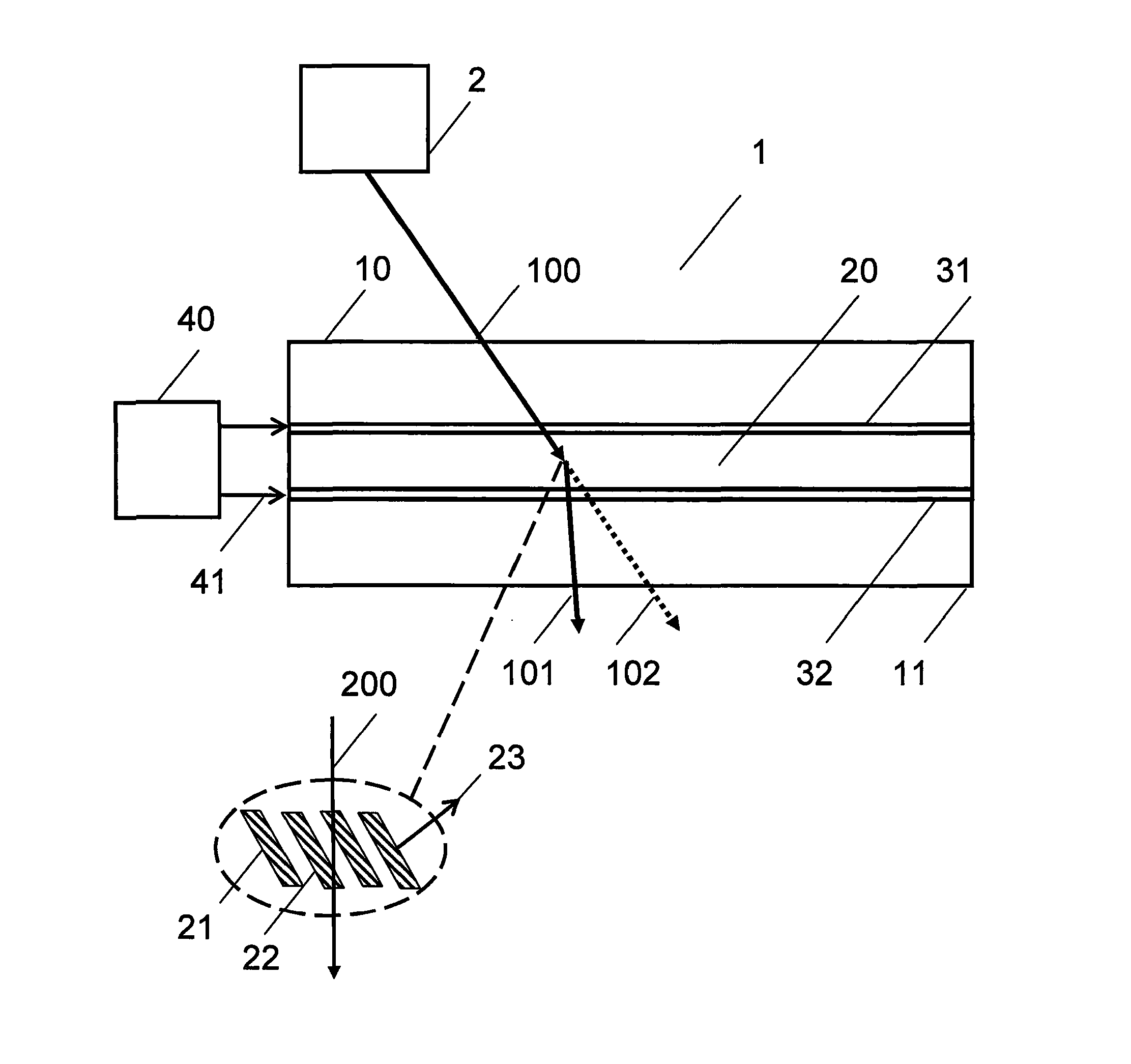
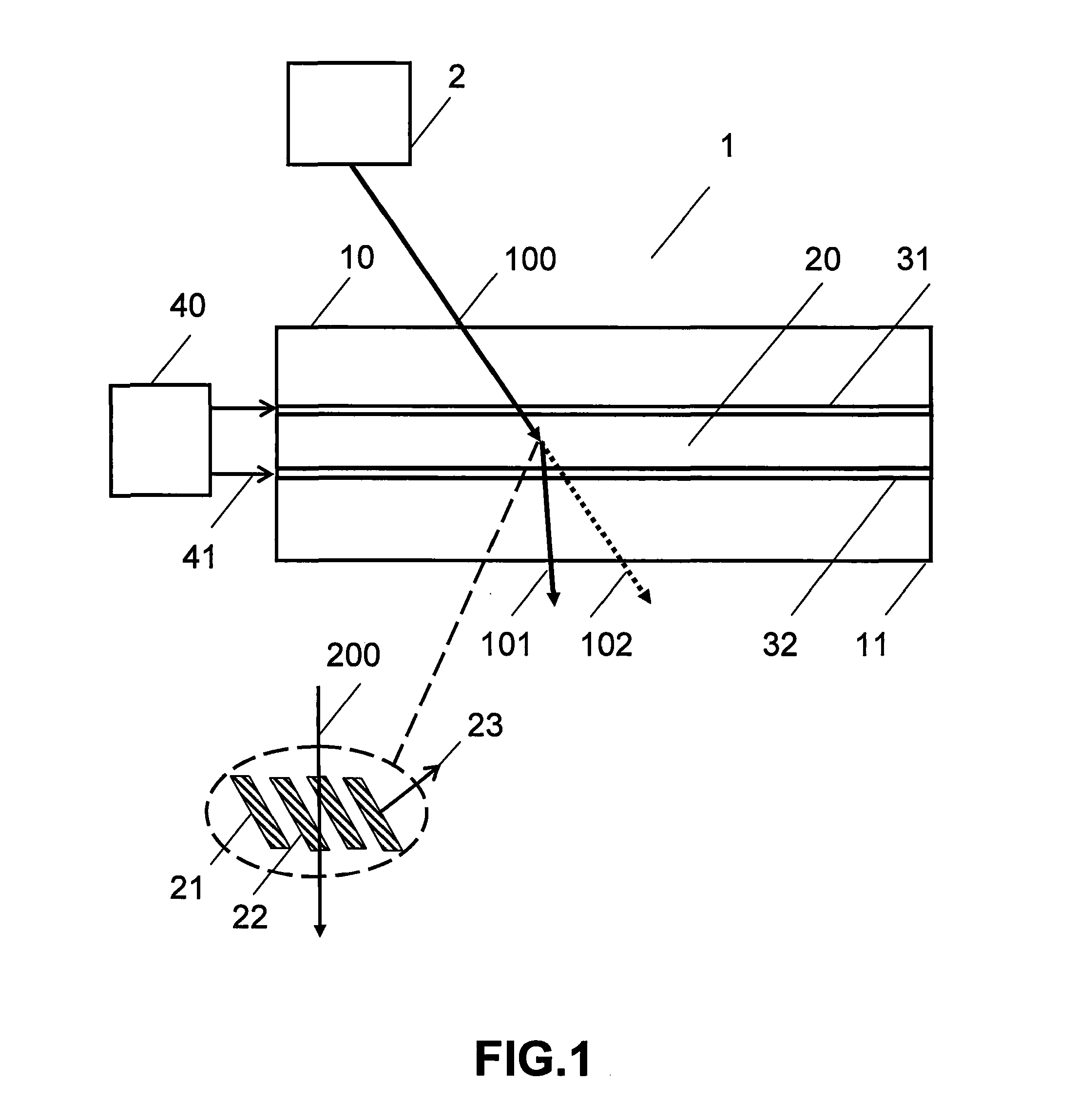
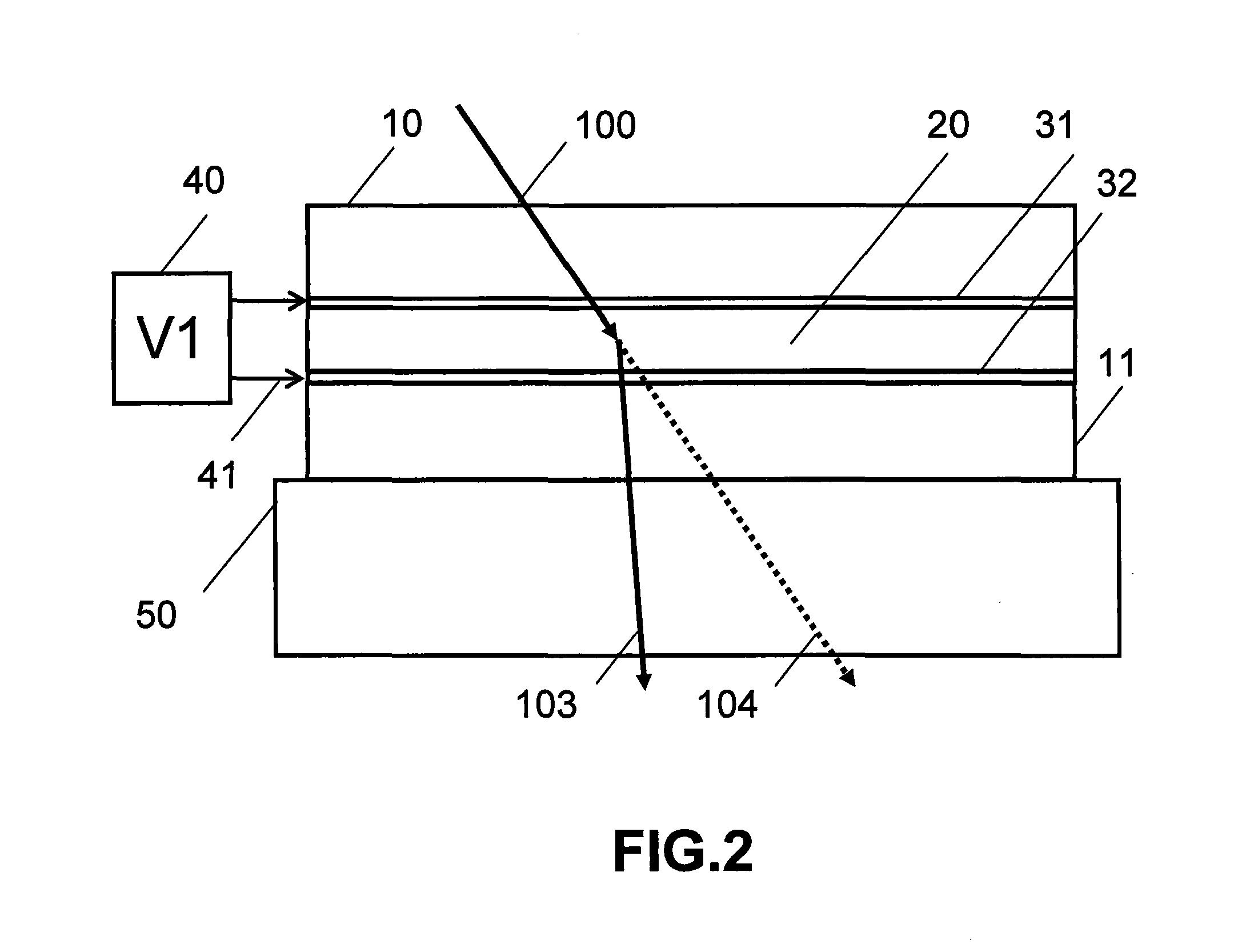
The invention describes a way to make better holograms for use in holographic replication processes. The invention involves using a master hologram that has more precise control over its refractive index modulation. The invention includes a holographic recording apparatus with a source of illumination, a master hologram, and a copy substrate. An applied voltage is used to change the refractive index modulation of at least one of the master hologram or the copy substrate. The master hologram diffracts the illumination light and diffracted light interfere in the copy substrate to form a copy of the master hologram. The invention can produce spatial variations in the refractive index modulation using the applied voltage. The master hologram can be a photo thermal refractive, SBG, or a reverse mode SBG. The copy substrate can be made from optical plastic or formed as a mechanically translatable continuous lamina. The refractive index modulation can be controlled to improve the quality of the hologram.

Problems solved by technology

A volume phase grating is then recorded by illuminating the liquid material with two mutually coherent laser beams, which interfere to form the desired grating structure.
Currently available holographic mastering process suffer from the problem that the relative intensities of the diffracted and zero orders cannot be controlled to better than ±5%.
However, the inventors have found that making a perfect master with the appropriate level of over-modulation, which is typically 5-10%, is very difficult in practice.

Method used


Image

  • Apparatus for copying a hologram
  • Apparatus for copying a hologram
  • Apparatus for copying a hologram

Examples


Embodiment Construction

[0045]The invention will now be further described by way of example only with reference to the accompanying drawings. It will apparent to those skilled in the art that the present invention may be practiced with some or all of the present invention as disclosed in the following description. For the purposes of explaining the invention well-known features of optical technology known to those skilled in the art of optical design and visual displays have been omitted or simplified in order not to obscure the basic principles of the invention. Unless otherwise stated the term “on-axis” in relation to a ray or a beam direction refers to propagation parallel to an axis normal to the surfaces of the optical components described in relation to the invention. In the following description the terms light, ray, beam and direction may be used interchangeably and in association with each other to indicate the direction of propagation of light energy along rectilinear trajectories. Parts of the f...


PUM

PropertyMeasurementUnit
internal incidence angleaaaaaaaaaa
internal incidence anglesaaaaaaaaaa
thicknessaaaaaaaaaa

Abstract

A holographic recording apparatus having a source of illumination, a master hologram containing at least one hologram lamina overlaying, a copy substrate containing a holographic recording medium, and a voltage generator for applied a voltage across at least one of the master hologram and the copy substrate. The master hologram diffracts the illumination light into zero order light and diffracted light which interfere in the copy substrate to form a copy of the master hologram. The source of illumination is applied for a predefined exposure time during which the voltage varies the refractive index modulation of at least one of the master hologram and the copy hologram.

Description

CROSS REFERENCE TO RELATED APPLICATIONS[0001]This application claims priority from U.S. Provisional Application Ser. No. 61 / 690,014 with filing date 18 Jun. 2012 entitled ELECTRICALLY CONTROLLABLE MASTER HOLOGRAM FOR CONTACT COPYING, which is hereby incorporated by reference in its entirety.[0002]The following patent applications are incorporated by reference herein in their entireties:[0003]U.S. Provisional Patent Application No. 61 / 687,436 with filing date 25 Apr. 12 entitled WIDE ANGLE COLOUR HEAD MOUNTED DISPLAY;[0004]U.S. Provisional Patent Application No. 61 / 689,907 with filing date 25 Apr. 12 entitled HOLOGRAPHIC HEAD MOUNTED DISLAY WITH IMPROVED IMAGE UNIFORMITY;[0005]U.S. Provisional Application No. 61 / 796,632 with filing date 16 Oct. 2012 entitled TRANSPARENT DISPLAYS BASED ON HOLOGRAPHIC SUBSTRATE GUIDED OPTICS;[0006]U.S. Provisional Application No. 61 / 849,853 with filing date 4 Feb. 2013 entitled TRANSPARENT WAVEGUIDE DISPLAY;[0007]PCT Application No.: US2008 / 001909, wit...

Claims


Application Information

Patent Timeline
Patent Type & Authority Applications(United States)
IPC IPC(8): G03H1/20
CPCG03H1/20G03H2001/0489G02F1/13342G03H1/0256G03H1/202G03H1/22G03H1/30G03H2001/205G03H2240/52G03H2260/12G03H2260/33
Inventor POPOVICH, MILAN MOMCILOWALDERN, JONATHAN DAVID
Owner DIGILENS
Learn More