Controlled liquid/solid mobility using external fields on lubricant-impregnated surfaces

a technology of lubricant impregnated surfaces and external fields, which is applied in the direction of solar heat collectors with working fluids, magnetic materials, solar thermal energy generation, etc., can solve the problems of dramatic reduction in panel efficiency, optimize energy transfer, and improve droplet slippage. , the effect of facilitating the shedding of both moisture and dus

Inactive Publication Date: 2015-06-25
MASSACHUSETTS INST OF TECH
View PDF2 Cites 17 Cited by
  • Summary
  • Abstract
  • Description
  • Claims
  • Application Information

AI Technical Summary

Benefits of technology

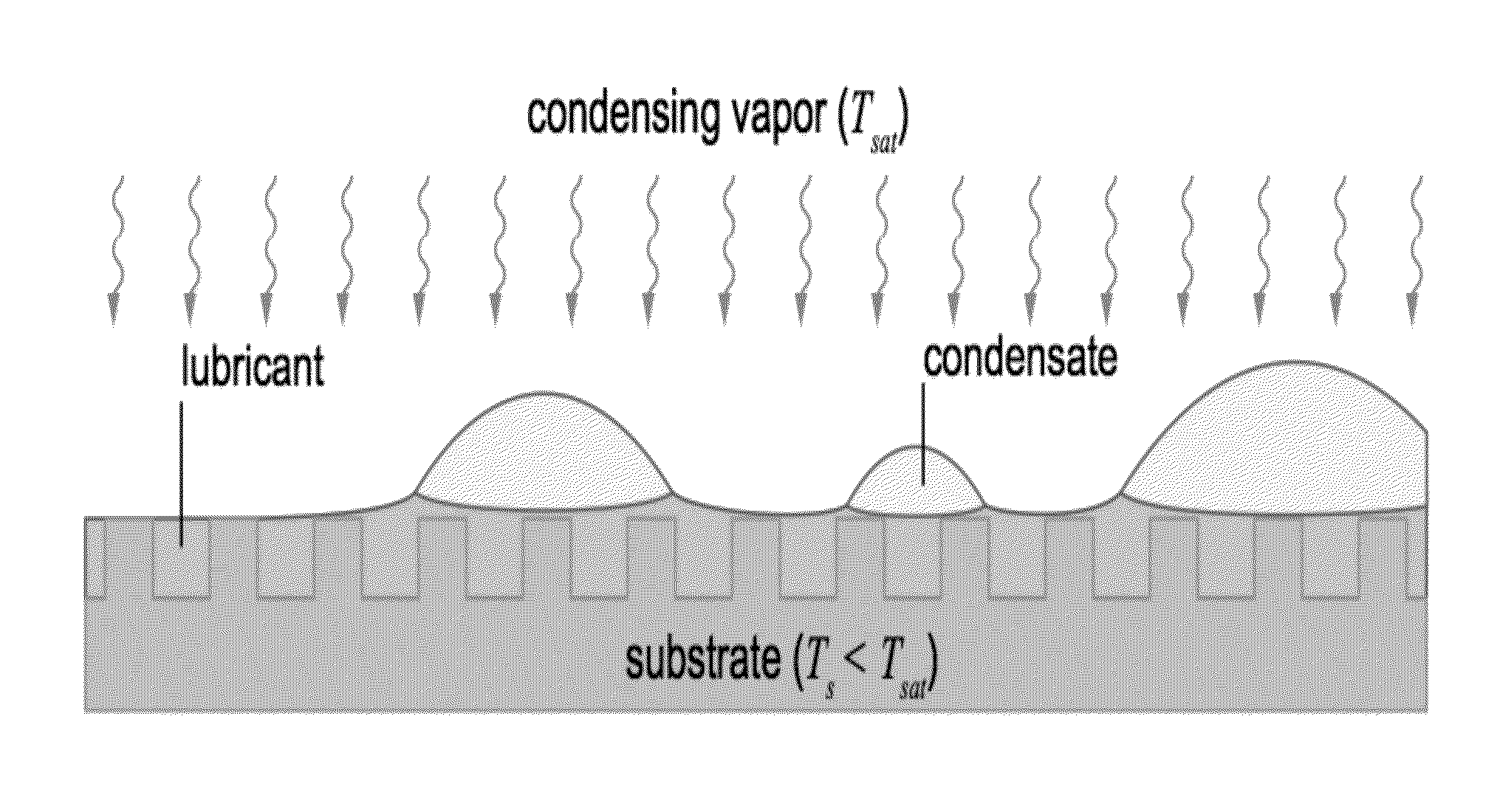
[0008]Described herein, in certain embodiments, are systems and methods for controlling / manipulating the movement of droplets (e.g., liquid droplets) on surfaces (e.g., non-wetting surfaces). In some embodiments, the droplets move over a lubricant-impregnated surface, which enhances or improves the slippage of droplets. An external electrical and / or magnetic field is applied to a lubricant-impregnated surface, thereby optimizing energy transfer and allowing precise control of the movement of a motive phase(s) (e.g., liquid droplets) on the surface (including, e.g., precise control of the trajectory and / or the speed of the movement of the motive phase). In certain embodiments, the invention facilitates shedding of both moisture and dust from critical energy system surfaces. In some embodiments, critical energy system surfaces include condenser surfaces (shedding small droplets instead of allowing filmwise condensation to occur), solar panels (droplets / dust will cause light diffraction and decrease efficiency of panel dramatically). Both of these are “energy systems”, both of which need droplets to be shed.

Problems solved by technology

In some embodiments, critical energy system surfaces include condenser surfaces (shedding small droplets instead of allowing filmwise condensation to occur), solar panels (droplets / dust will cause light diffraction and decrease efficiency of panel dramatically).

Method used


Image

  • Controlled liquid/solid mobility using external fields on lubricant-impregnated surfaces
  • Controlled liquid/solid mobility using external fields on lubricant-impregnated surfaces
  • Controlled liquid/solid mobility using external fields on lubricant-impregnated surfaces

Examples


Embodiment Construction

Materials and Methods

[0104]Ferrotec EMG 901 ferrofluid was used for ferrofluid, which includes nominal magnetite particle diameter of 10 nanometers at concentration of 11.8% volume. The ferrofluid has a saturation magnetization of 660 Gauss and a viscosity of 8 cP at 27° C.

[0105]K&J Magnetics 3 mm radius cylindrical neodymium permanent magnet (Grade N52) were used as permanent magnets

Electric Field Experiments

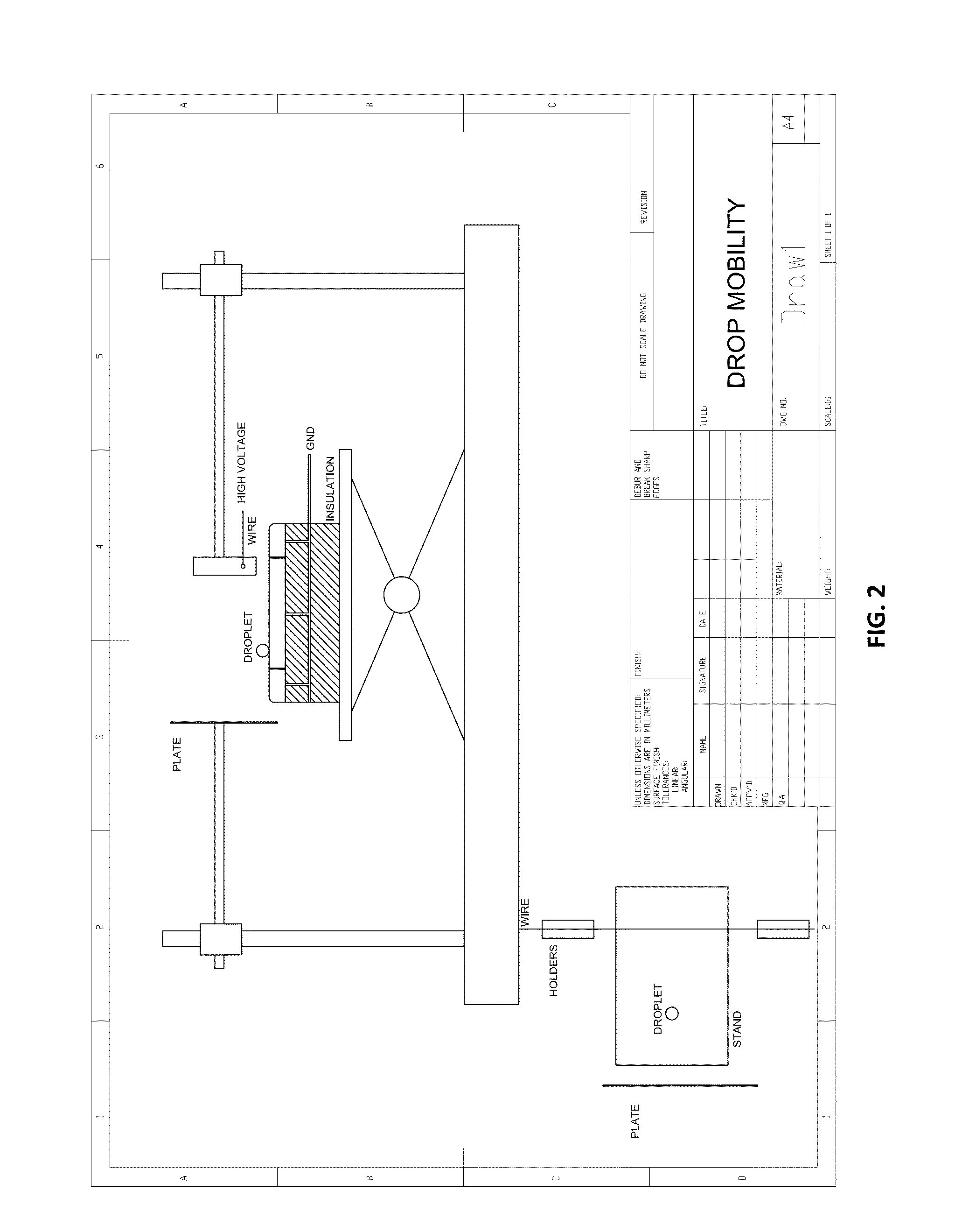
[0106]For both FIGS. 5 and 6, the samples that were used were identical. Silicon wafers were textured using typical clean-room photolithography and RIE (reactive-ion etching). Once the samples were textured, they were coated with a low surface energy silane (octadecyltrichlorosilane (OTS)) which rendered the surface hydrophobic and preferentially wetted by oil. OTS exhibits an advancing water contact angle of 110±4° on a smooth surface. The samples were impregnated using a careful dip coating technique at a controlled rate such that there was no excess oil. The oil used in both...


PUM

PropertyMeasurementUnit
vapor pressureaaaaaaaaaa
surface energiesaaaaaaaaaa
vapor pressuresaaaaaaaaaa

Abstract

A method for precise control of movement of a motive phase on a lubricant-impregnated surface includes providing a lubricant-impregnated surface, introducing the motive phase onto the lubricant-impregnated surface, and exposing the droplets to an electric and / or magnetic field to induce controlled movement of the droplets on the surface. The lubricant-impregnated surface includes a matrix of solid features spaced sufficiently close to stably contain the impregnating lubricant therebetween or therewithin. The motive phase is immiscible or scarcely miscible with the impregnating lubricant.

Description

CROSS-REFERENCE TO RELATED APPLICATIONS[0001]This application claims priority to, and the benefit of, and incorporates herein by reference in its entirety U.S. Provisional Patent Application No. 61 / 919,481, filed Dec. 20, 2013.TECHNICAL FIELD[0002]This invention relates generally to articles, devices, and methods for controlling the movement of liquids and solids on lubricant-impregnated surfaces.BACKGROUND[0003]The ability to control the movement of motive phases (e.g., droplets) on surfaces (e.g., non-wetting surfaces) is highly desirable for a wide variety of diverse applications including, for example, micro-fluidic devices, anti-icing, dropwise condensation, and biomedical devices. For example, conventional lab-on-a-chip (LOC) devices integrate one or more laboratory functions on a single, small chip and are useful in performing diagnostic tests. These devices permit the handling of very small fluid volumes, e.g., volumes of a picoliter or less, via prefabricated microchannels ...

Claims


Application Information

Patent Timeline
Patent Type & Authority Applications(United States)
IPC IPC(8): H01F1/44F04B19/00
CPCH01F1/442H01F1/445F04B19/006B01L3/502707B01L3/502792B01L2300/0816B01L2300/161B01L2300/166B01L2400/0415B01L2400/043B64D15/06C09D5/00C09D5/1687C09D5/23C09D5/24F28F13/04F28F13/16F28F19/00F24S40/20F24S40/42Y02E10/10Y02E10/44Y10T428/13Y10T137/0391C09D5/1681F24S10/70F24T10/13Y02E10/40
Inventor KHALIL, KARIM SAMIRVARANASI, KRIPA KIRANMAHMOUDI, SEYED REZA
Owner MASSACHUSETTS INST OF TECH
Why Eureka
Try Eureka