Coaxial cable connector and threaded connector

a technology of threaded connectors and coaxial cables, which is applied in the direction of television connectors, two-part coupling devices, and connection of coupling devices, etc., can solve the problems of unqualified properties of threaded connectors, unqualified electrical connections, and unqualified electrical connections, so as to avoid unqualified electrical connections and good electrical connections

Active Publication Date: 2015-06-25
EZCONN
View PDF1 Cites 36 Cited by
  • Summary
  • Abstract
  • Description
  • Claims
  • Application Information

AI Technical Summary

Benefits of technology

[0007]The present invention provides a coaxial cable connector with a metal sheet arranged at a nut thereof, an inner sleeve thereof or an outer sleeve thereof and a threaded connector of an electronic device with a metal sheet. The met...

Problems solved by technology

The conventional screw-on F-type coaxial cable connector may often not have good ground connection because the F-type coaxial cable connector has a nut, when being screwed with a threaded connector, which may have a loose contact wit...

Method used


Image

  • Coaxial cable connector and threaded connector
  • Coaxial cable connector and threaded connector
  • Coaxial cable connector and threaded connector

Examples


first embodiment

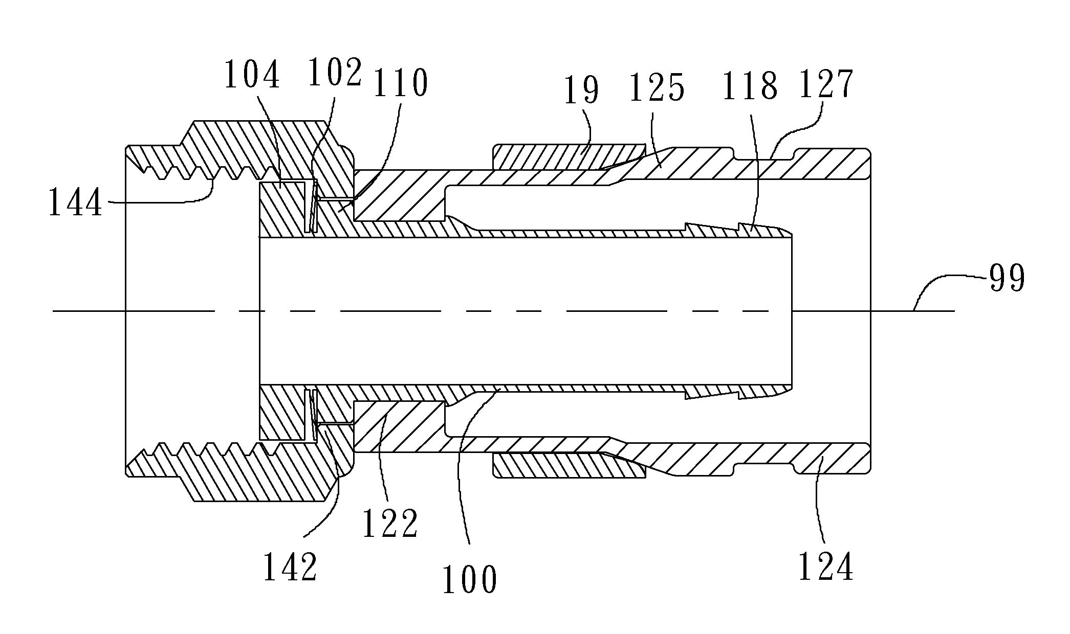
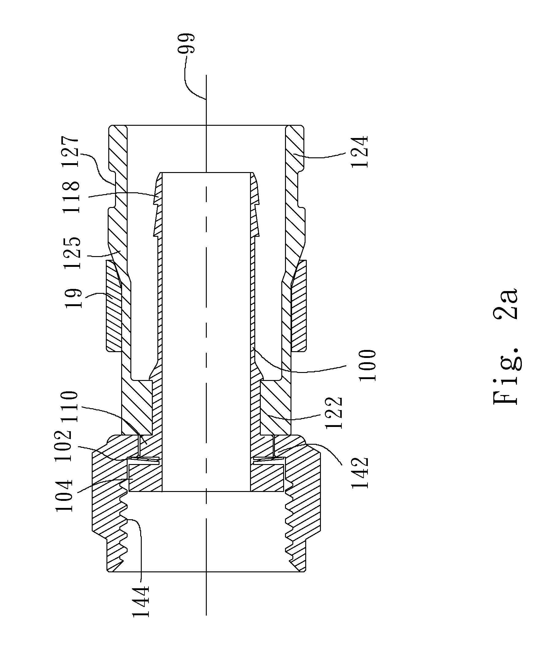
[0086]FIG. 2a is a cross-sectional view showing a coaxial cable connector in accordance with a first embodiment of the present invention. FIG. 2b is a cross-sectional exploded view showing the coaxial cable connector in accordance with the first embodiment of the present invention. FIG. 2c is a perspective view showing an inner sleeve in accordance with the first embodiment of the present invention. FIG. 2i is a front view showing positions of bending lines of two metal sheets relative to the inner sleeve in accordance with the first embodiment of the present invention. Referring to FIGS. 2a, 2b, 2c and 2i, the coaxial cable connector includes an inner sleeve 10, an outer sleeve 12, a nut 14 and a metal ring 19 coaxially arranged with respect to an axis 99 of the inner sleeve 10. Either one of the inner sleeve 10, nut 14 and metal ring 19 may be made of an electrically conductive material, such as copper, iron, silver, nickel, tin, gold, a copper-gold alloy, a copper-tin alloy, a co...

second embodiment

[0099]FIG. 3a is a cross-sectional view showing a coaxial cable connector in accordance with a second embodiment of the present invention. FIG. 3b is a cross-sectional view showing an inner sleeve in accordance with the second embodiment of the present invention. FIG. 3f is a front view showing positions of bending lines of two metal sheets relative to the inner sleeve in accordance with the second embodiment of the present invention. Elements in the second embodiment having the same reference number as those in the first embodiment may refer to those illustrated in the first embodiment. Referring to FIGS. 3a, 3b and 3f, the difference between the first and second embodiments is that the inner sleeve 10 in the second embodiment has no second empty gaps 108 illustrated in the first embodiment in the second outer flange 110 at the border between the first outer flange 104 and the second outer flange 110. A blade may be used to cut into the inner sleeve 10 from the first outer flange 1...

third embodiment

[0107]FIG. 4a is a cross-sectional view showing a coaxial cable connector in accordance with a third embodiment of the present invention. FIG. 4b is a cross-sectional exploded view showing the coaxial cable connector in accordance with the third embodiment of the present invention. FIG. 4c is a perspective view showing an inner sleeve in accordance with the third embodiment of the present invention. FIG. 4i is a front view showing positions of bending lines relative to the inner sleeve with two metal sheets before bent along the bending line in accordance with the third embodiment of the present invention. Elements in the third embodiment having the same reference number as those in the first embodiment may refer to those illustrated in the first embodiment. Referring to FIGS. 4a, 4b, 4c and 4i, the outer sleeve 12, nut 14 and metal ring 19 in accordance with the third embodiment may be referred to those in accordance with the first embodiment. The inner sleeve 30 in accordance with...


PUM


Abstract

An coaxial cable connector is configured to engage with an outer thread of a threaded connector. The coaxial cable connector comprises an inner sleeve, an outer sleeve arranged around the inner sleeve and a nut arranged around the inner sleeve. The nut comprises a metal sheet integral with an inner flange of the nut, wherein the metal sheet is between the inner flange and a cylindrical surface of the inner sleeve. The metal sheet has a fixed side, close to an outer flange of the inner sleeve, fixed to the inner flange of the nut, and a free side, away from the outer flange of the inner sleeve, abutting against the cylindrical surface of the inner sleeve. An empty gap is between the metal sheet and the inner flange. When the nut comprises an inner thread engaging with the outer thread, the outer flange is configured to be between the inner flange and the threaded connector.

Description

[0001]The present application claims priority to TW application No. 102224143, filed on Dec. 20, 2013 and TW application No. 103201941, filed on Jan. 29, 2014, all of which is incorporated herein by reference.BACKGROUND OF THE DISCLOSURE[0002]1. Field of the Disclosure[0003]The disclosure relates to a coaxial cable connector and threaded connector, and more particularly, to a coaxial cable connector and threaded connector with improved electrical connection.[0004]2. Brief Description of the Related Art[0005]Currently, with regards to signal reception, coaxial cables are a mainstream to be employed for televisions (TV). A cable television may receive signals via a coaxial cable. The coaxial cable may include a screw-on F-type connector to be connected with a cable TV decoder, a video cassette recorder (VCR), a digital hard-disk recorder for a digital versatile disc (DVD), a satellite receiver, a video game, a TV signal distribution splitter or a switch.[0006]The conventional screw-on...

Claims


Application Information

Patent Timeline
IPC IPC(8): H01R9/05
CPCH01R9/0521H01R9/0524H01R13/622H01R13/025H01R24/38H01R2201/18H01R4/48
Inventor WEI, KAI-CHIH
Owner EZCONN
Why Eureka
Try Eureka