Clamps for solar systems

a solar system and clamping technology, applied in the direction of heat collector mounting/support, pv power plants, lighting and heating equipment, etc., can solve problems such as difficulty in coupleing modules

Active Publication Date: 2015-06-25
SUNPOWER CORPORATION
View PDF11 Cites 54 Cited by
  • Summary
  • Abstract
  • Description
  • Claims
  • Application Information

AI Technical Summary

Benefits of technology

[0009]In one embodiment, a clamp assembly having a major axis is disclosed. The clamp assembly can include an upper clamp member and a lower clamp member. The clamp assembly can further include a stabilization member having a relaxed state and one or more compressed states. The stabilization member can be configure...

Problems solved by technology

It can be challenging to couple modules side-by-side because the array assembler typically engages the...

Method used


Image

  • Clamps for solar systems
  • Clamps for solar systems
  • Clamps for solar systems

Examples


Embodiment Construction

[0053]The following detailed description is merely illustrative in nature and is not intended to limit the embodiments of the subject matter or the application and uses of such embodiments. As used herein, the word “exemplary” means “serving as an example, instance, or illustration.” Any implementation described herein as exemplary is not necessarily to be construed as preferred or advantageous over other implementations. Furthermore, there is no intention to be bound by any expressed or implied theory presented in the preceding technical field, background, brief summary or the following detailed description.

[0054]This specification includes references to “one embodiment” or “an embodiment.” The appearances of the phrases “in one embodiment” or “in an embodiment” do not necessarily refer to the same embodiment. Particular features, structures, or characteristics may be combined in any suitable manner consistent with this disclosure.

[0055]“Configured To.” Various units or components ...


PUM

PropertyMeasurementUnit
Weightaaaaaaaaaa
Lengthaaaaaaaaaa
Widthaaaaaaaaaa

Abstract

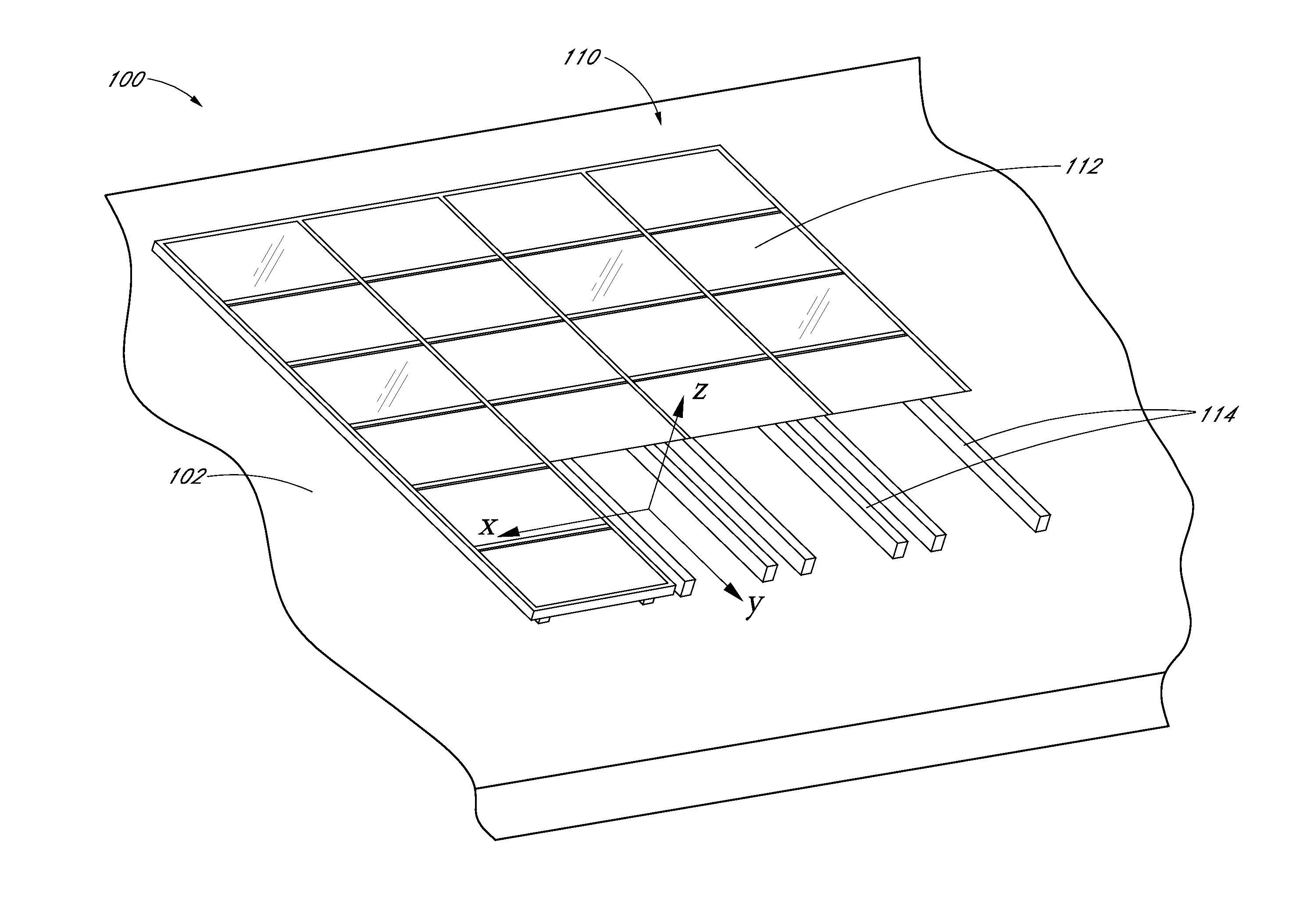
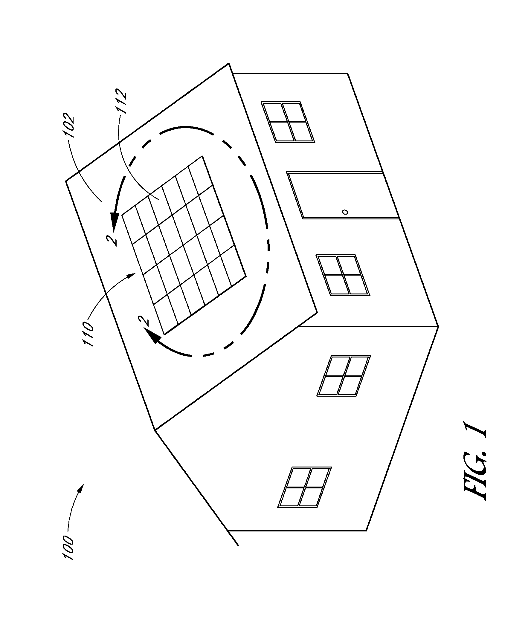
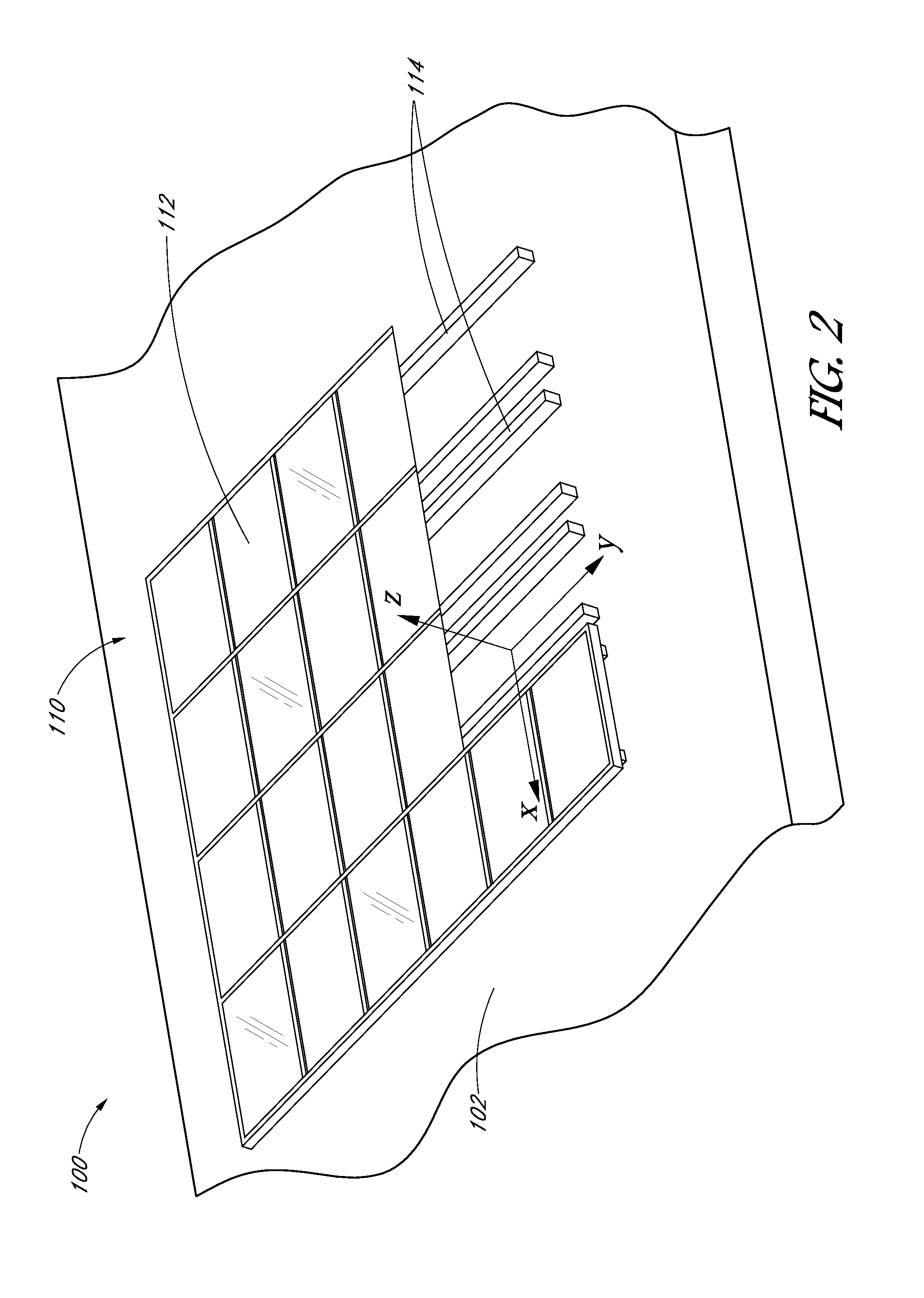
A solar power system can include a rail and a solar module disposed on the rail. A clamp assembly can couple the solar module to the rail. The clamp assembly can have a clamped configuration in which the solar module is secured to the rail and an unclamped configuration. The clamp assembly can comprise an upper clamp member, a lower clamp member coupled to the rail, and a stabilization member mechanically engaging the upper clamp member and the lower clamp member. The stabilization member can prevent rotation of the lower clamp member relative to the rail when the clamp assembly is in the clamped and unclamped configurations. In the unclamped configuration, the stabilization member can be biased such that the upper clamp member is disposed at a sufficient clearance above the rail to permit the insertion of the solar module between the upper clamp member and the rail.

Description

BACKGROUND[0001]1. Technical Field[0002]Embodiments of the subject matter described herein relate generally to improved clamps for solar systems, such as clamps for mounting solar modules to a mounting structure.[0003]2. Description of the Related Art[0004]Solar power has long been viewed as an important alternative energy source. To this end, substantial efforts and investments have been made to develop and improve upon solar energy collection technology. Of particular interest are residential-, industrial- and commercial-type applications in which relatively significant amounts of solar energy can be collected and utilized in supplementing or satisfying power needs. One way of implementing solar energy collection technology is by assembling an array of multiple solar modules.[0005]One type of solar energy system is a solar photovoltaic system. Solar photovoltaic systems (“photovoltaic systems”) can employ solar panels made of silicon or other materials (e.g., III-V cells such as G...

Claims


Application Information

Patent Timeline
IPC IPC(8): H02S20/23F16B2/12H01L31/18
CPCH02S20/23F16B2/12H01L31/18H02S30/10Y02B10/20Y02E10/47F24S2025/016Y10T24/44265Y10T24/44641Y10T24/44Y10T24/44017Y10T29/49355F24S25/70F24S25/60F24S25/33F24S25/636Y02E10/50Y02B10/10F24S25/00F24S25/30F24S25/634
Inventor BRAUNSTEIN, RYANKINYON, ZACHARYCARRE, GUILLAUMEMATRAT, DAVID
Owner SUNPOWER CORPORATION
Why Eureka
Try Eureka