
Wearable apparatus for delivery of power to a retinal prosthesis

a technology for retinal prosthesis and wearable equipment, which is applied in the direction of instruments, artificial respiration, therapy, etc., can solve the problems of retinal malfunction, blindness and visual impairment,

Active Publication Date: 2015-07-02
NANO RETINA LTD
View PDF2 Cites 36 Cited by
  • Summary
  • Abstract
  • Description
  • Claims
  • Application Information

AI Technical Summary

Benefits of technology

The patent describes an apparatus that can switch between a transmitting mode and a reflecting mode to control the distribution of light from a beam of light. In the transmitting mode, the apparatus allows light from the beam to pass through and enter the subject's eye. In the reflecting mode, the apparatus prevents light from entering the eye. This technology can be useful for applications such as laser surgery or optical imaging.

Problems solved by technology

Retinal malfunction, due to degenerative retinal diseases, is a leading cause of blindness and visual impairment.

Method used


Image

  • Wearable apparatus for delivery of power to a retinal prosthesis
  • Wearable apparatus for delivery of power to a retinal prosthesis
  • Wearable apparatus for delivery of power to a retinal prosthesis

Examples


Embodiment Construction

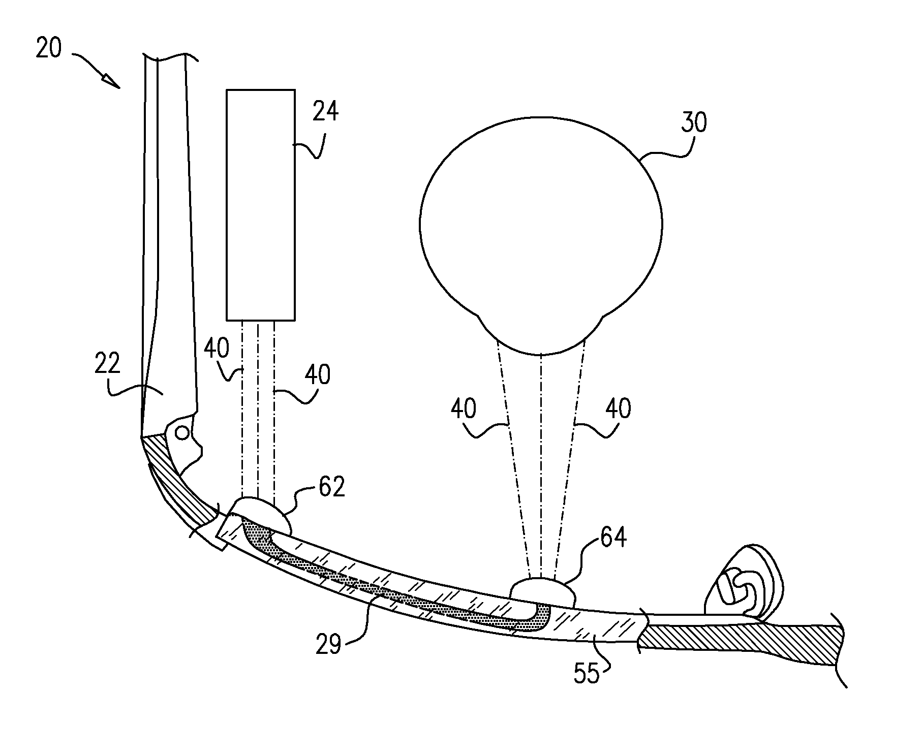
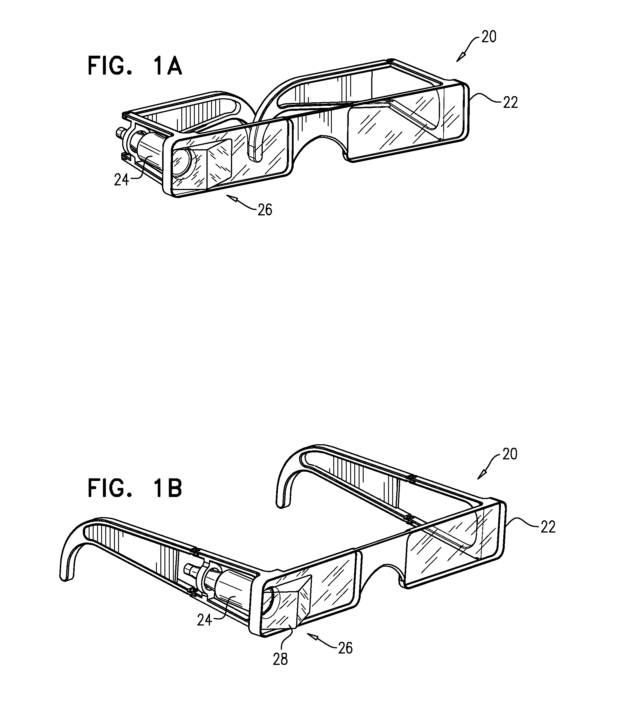
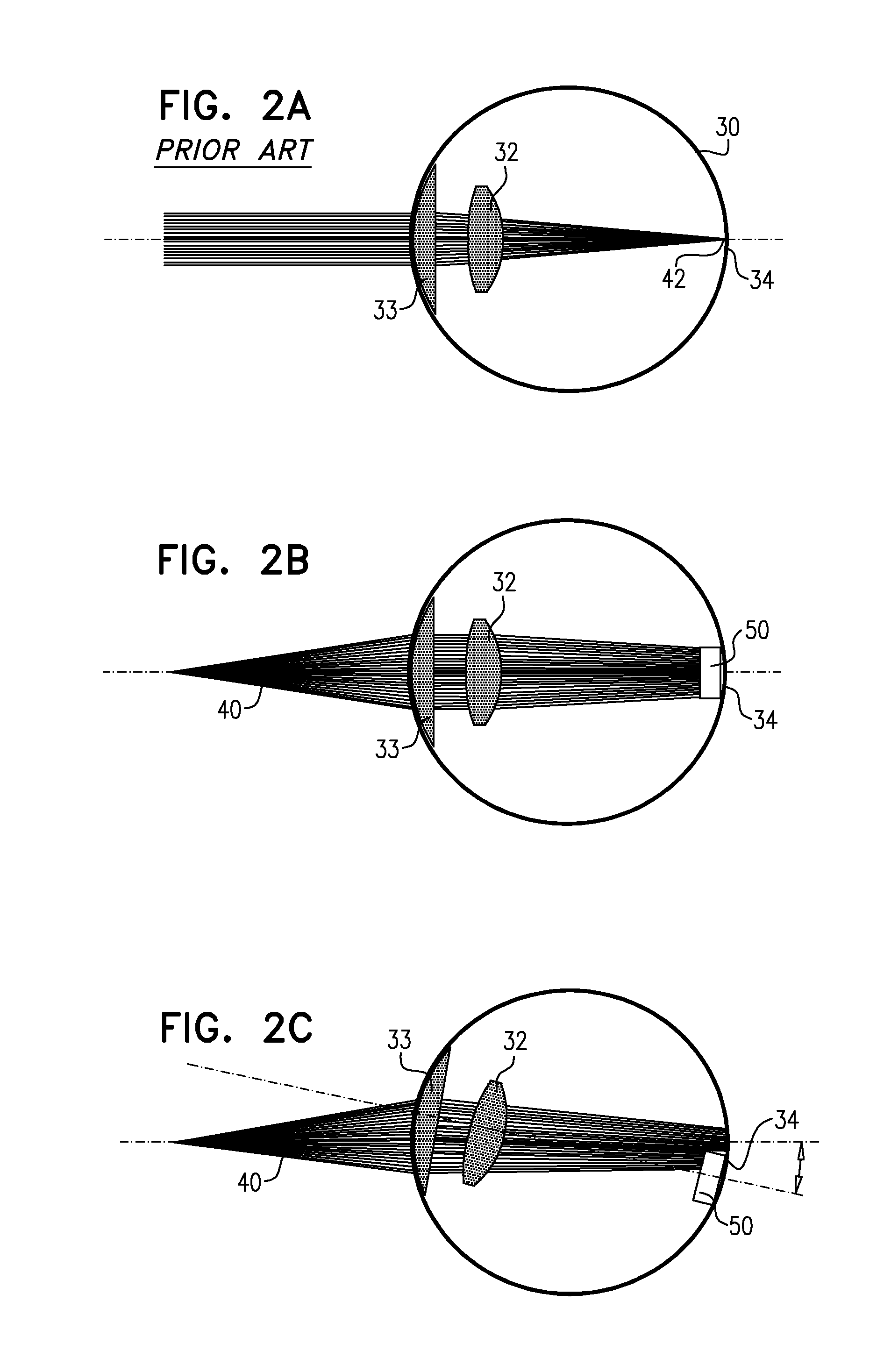
[0138]Reference is made to FIGS. 1A-B and 2A-C. FIGS. 1A-B are schematic illustrations of apparatus comprising an extraocular device 20, in accordance with some applications of the present invention. Extraocular device 20 typically comprises an eyeglasses frame 22, which is placed in front of an eye of a subject. A power source 24, e.g., a laser, is coupled to frame and emits a beam of light, e.g., a collimated beam, a diverging beam, or a converging beam, that is outside of the visible light range, e.g., outside 380-750 nm. For example, the power source may be configured to emit the beam of light in the range of 750-900 nm. Typically the beam of light is configured to power an intraocular device, e.g., a retinal prosthesis, which is implanted in the subject's eye. The intraocular device is typically configured to receive the beam of light from the power source and to generate a power signal to power the intraocular device.

[0139]Typically, a light-guiding element 26, e.g., a prism (...


PUM


Abstract

Apparatus is provided including an extraocular device, which includes an eyeglasses frame, which is placed in front of an eye of a subject, and a power source coupled to the eyeglasses frame and configured to emit a beam of light that is outside of 380-750 nm. A light-guiding element is coupled to the eyeglasses frame and at least one optical coupling-in element and at least one optical coupling-out element are optically coupled to the light-guiding element. The coupling-in element is positioned such that the beam of light is directed into the light-guiding element via the coupling-in element, and the coupling-in and coupling-out elements are positioned such that the beam diverges from a focal point located within 3 mm of the coupling-out element. Other applications are also described.

Description

FIELD OF THE APPLICATION[0001]Applications of the present invention relate generally to powering of an implantable medical device, and specifically to supplying power to a retinal prosthesis.BACKGROUND OF THE APPLICATION[0002]Retinal malfunction, due to degenerative retinal diseases, is a leading cause of blindness and visual impairment. Implantation of a retinal prosthesis is a technology for restoring some useful vision in individuals suffering from retinal-related blindness.[0003]Implantable medical devices, e.g., a retinal prosthesis, typically require a source of energy in order to function. Battery-less, wireless power transfer technologies provide a useful way to power an implantable medical device.SUMMARY OF APPLICATIONS[0004]Some applications of the present invention comprise apparatus comprising an extraocular device having an eyeglasses frame, which is placed in front of an eye of a subject. A power source, e.g., a laser, is coupled to the eyeglasses frame and emits a bea...

Claims


Application Information

Patent Timeline
Patent Type & Authority Applications(United States)
IPC IPC(8): A61N1/36A61N1/378
CPCA61N1/3787A61N1/36046G02C7/086G02C11/10A61B2560/0219A61F2250/0001G02B2027/0178G02B2027/0187G02B27/0093G02B27/017G02B2027/0114G02B2027/0138G02B27/0172G02B6/34G02B6/4287G02B6/4295G02B6/0016G02B6/0055G02B6/26
Inventor GEFEN, RA'ANANYANOVITZ, LEONIDKAMINTZ, KOBIEISENBERG, SHAI
Owner NANO RETINA LTD
Learn More