
Eureka
For R&D, Eureka makes reading and utilizing patents & technical documents easy.
Eureka AIR
Designed for self-driven R&D workflows. Generate viable solutions, solve complex R&D challenges, empower your innovation with AI.

Eureka Materials
Designed for material experts only. Revolutionize your material R&D, from search, analyze, to developing new materials.

TechResearch
Generate reliable direction feasibility study reports for your R&D in just a few steps.

TechSeek
Discover and master advanced knowledge NOW. Basics, ideas, possibilities, all at once.

TechMind
As an expert in R&D Theories, TechMind can generates customized viable solutions instantly.

TechRisk
Analyze your overall solution with one click, know your potential R&D risks in advance.

TechMonitor
Get weekly tech updates, stay abreast of the latest tech innovations and key insights.
Cutter tooth for a saw chain
- Summary
- Abstract
- Description
- Claims
- Application Information
AI Technical Summary
Benefits of technology
Problems solved by technology
Method used
Image

Examples
Embodiment Construction
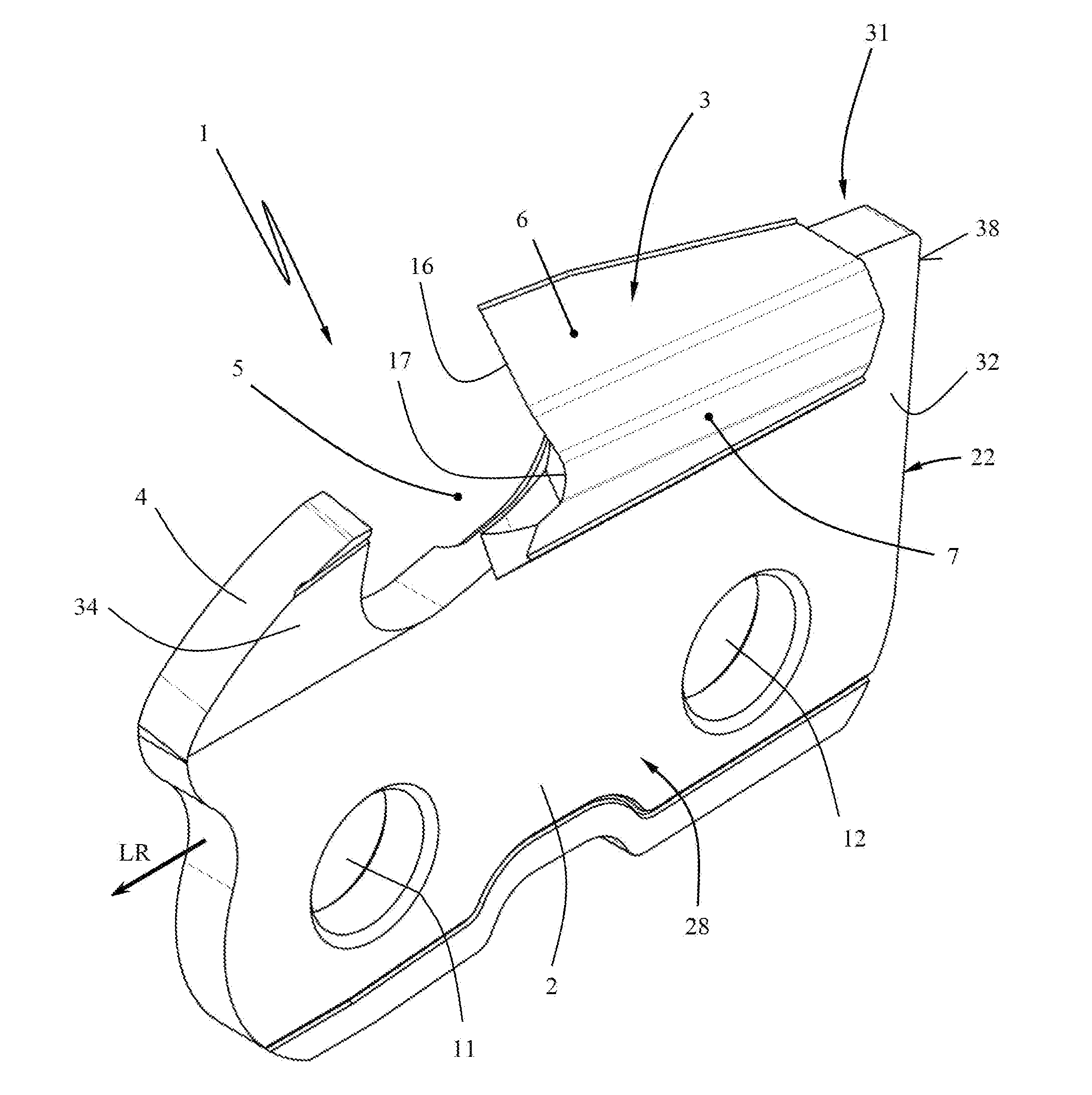
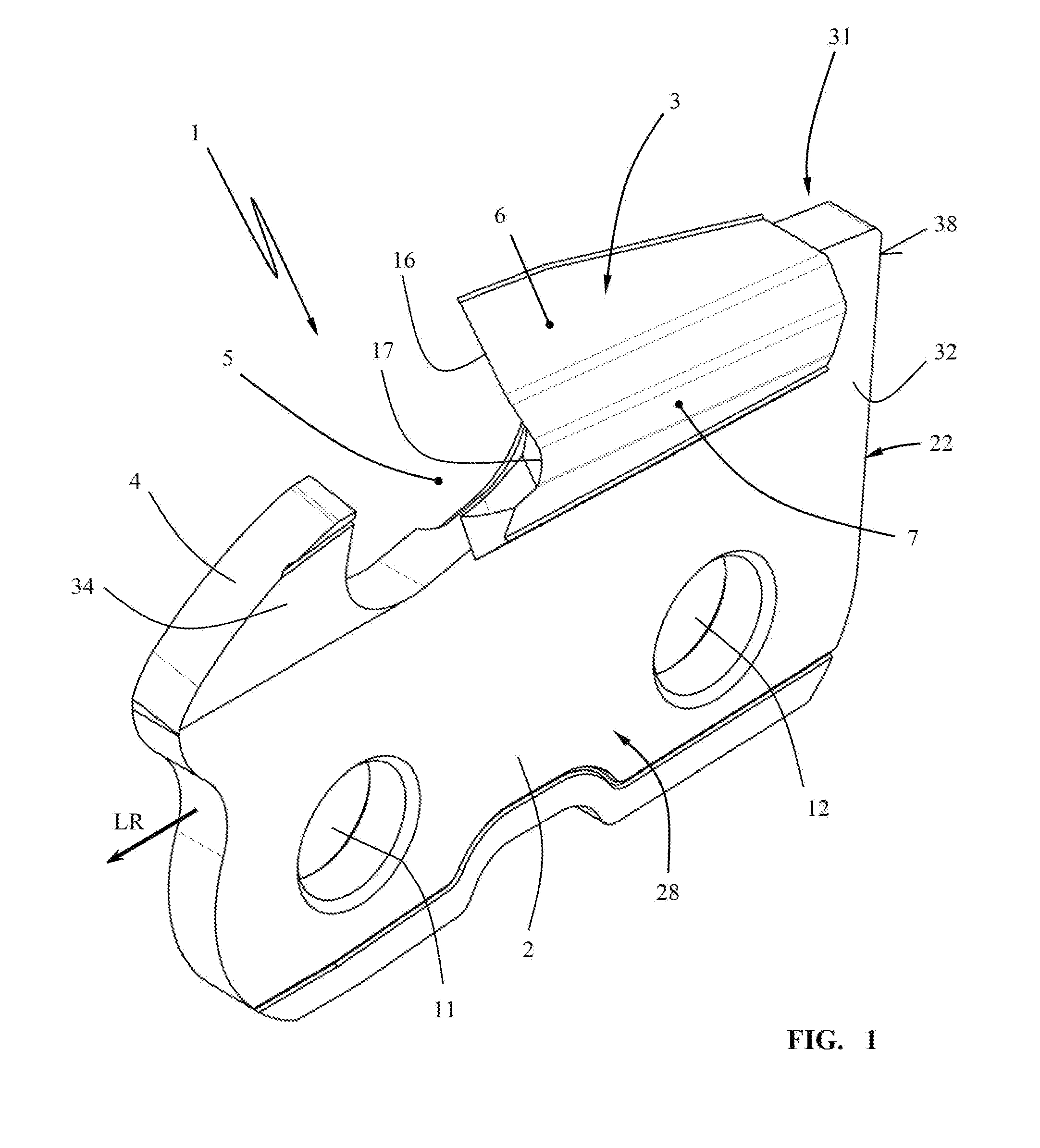
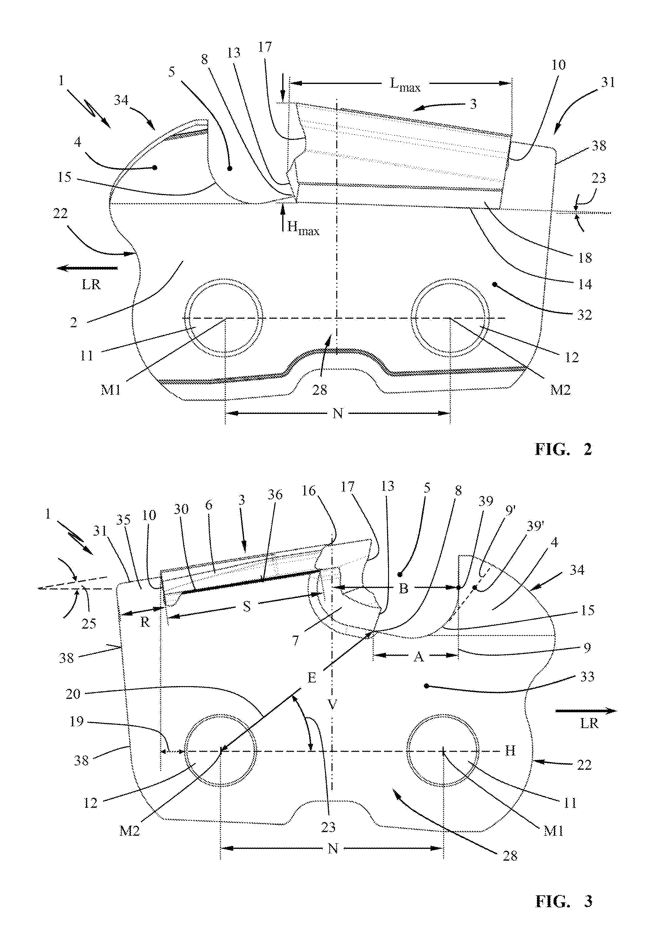
[0027]The cutter tooth 1 illustrated in the Figures comprises a base member 2 which is comprised substantially of a flat plate 22. The base member 2 comprises, as can be seen in particular in the side views of FIGS. 2 and 3, an upper edge 31 and a lower base area 28. In the lower base area 28, rivet openings 11 and 12 are formed in the plate 22 of the base member 2 (FIGS. 1 to 3) and are sequentially arranged in the running direction LR of the cutter tooth 1. The rivet opening 11 is a forward rivet opening leading in the running direction LR while the rivet opening 12 is a rear rivet opening trailing in the running direction LR.
[0028]As shown in FIGS. 2 and 3, each rivet opening has a center axis M1 and M2 positioned in the running direction LR at a rivet spacing N relative to each other.
[0029]At the upper edge 31 of the base member 2, a chip recess 5 is formed that extends between a depression 30 (FIG. 3) within the upper edge 31 and a residual web 34 that is forwardly positioned i...
PUM
| Property | Measurement | Unit |
|---|---|---|
| Fraction | aaaaa | aaaaa |
| Fraction | aaaaa | aaaaa |
| Fraction | aaaaa | aaaaa |
Abstract
Description
Claims
Application Information
 - R&D Engineer
- R&D Manager
- IP Professional
- Industry Leading Data Capabilities
- Powerful AI technology
- Patent DNA Extraction
Browse by: Latest US Patents, China's latest patents, Technical Efficacy Thesaurus, Application Domain, Technology Topic, Popular Technical Reports.
© 2024 PatSnap. All rights reserved.Legal|Privacy policy|Modern Slavery Act Transparency Statement|Sitemap|About US| Contact US: help@patsnap.com