
Drivetrain For Independent Suspension System

a technology of independent suspension and drivetrain, which is applied in the direction of propulsion parts, propulsion mounting, transportation and packaging, etc., can solve the problems of inherently limited articulation capability, interference would otherwise occur, and the second step is more difficult to address, so as to facilitate smooth, efficient and vibration-free transmission of power, the effect of minimizing the unsprung weigh

Inactive Publication Date: 2015-07-02
BANDY RONALD SCOTT
View PDF8 Cites 11 Cited by
  • Summary
  • Abstract
  • Description
  • Claims
  • Application Information

AI Technical Summary

Benefits of technology

The patent describes a suspension system for a vehicle that uses a long axle shaft and a vertical orientation of input and output shafts. The system also includes mounting brackets that act in cooperation with a reverse power coupler to align the flexible joints on the leading links with the ball joints attached to the knuckle. This design allows for a smooth and efficient transmission of power from the transfer case to the offset power coupler, resulting in a handling quality like an independent suspension system. By minimizing the angulation of the joints and mounting the differential housing to the frame, the system also provides strength and rigidity to the frame. Overall, the technical effects of the suspension system include improved handling, reduced weight, and improved stability and durability.

Problems solved by technology

When measured against a comparable solid axle, such an approach is inherently limited in articulation capability because the length of the control arms in a 4WD independent suspension system will always be less than one-half the length of the vehicle's track width.
However, addressing the second step is more challenging because the frame ends of the upper and lower leading links are attached to the opposite frame side, whereby the opposite frame side refers to the frame side opposite the one next to the wheel that the wheel ends of the upper and lower leading links are attached to.
This interference would otherwise occur due to the front drive shaft being used to transmit power from a location behind the transmission to the front differential housing, this location usually being a transfer case.
In general, the greater the angulation of the U or CV-joints in a drive shaft, then the greater is the wear and vibration associated with the drive shaft and the loss of efficiency in transmitting power via the drive shaft.
This alignment may be difficult to achieve when the one output shaft of the transfer case is offset from the longitudinal line and pinion shaft of the front differential housing is located on the longitudinal line, therefore resulting in a certain amount of drive shaft vibration.
In contrast, the location of the front differential housing on the longitudinal line can lead to wear and vibration problems in the drivetrain.

Method used


Image

  • Drivetrain For Independent Suspension System
  • Drivetrain For Independent Suspension System
  • Drivetrain For Independent Suspension System

Examples


Embodiment Construction

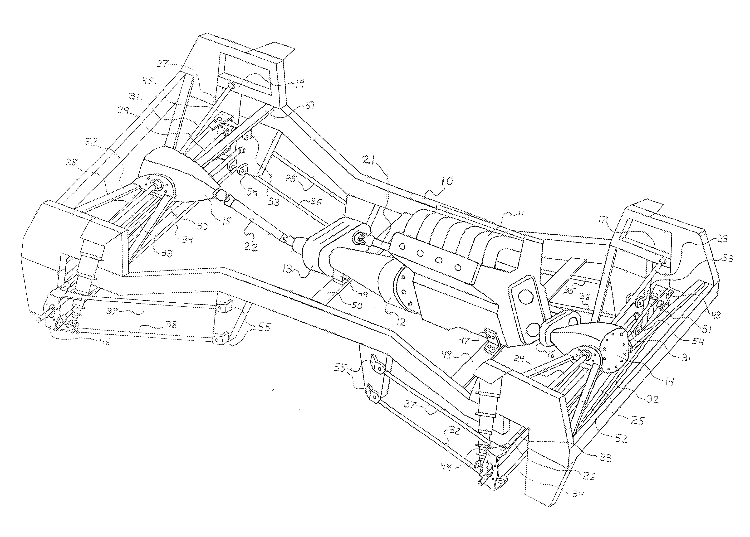
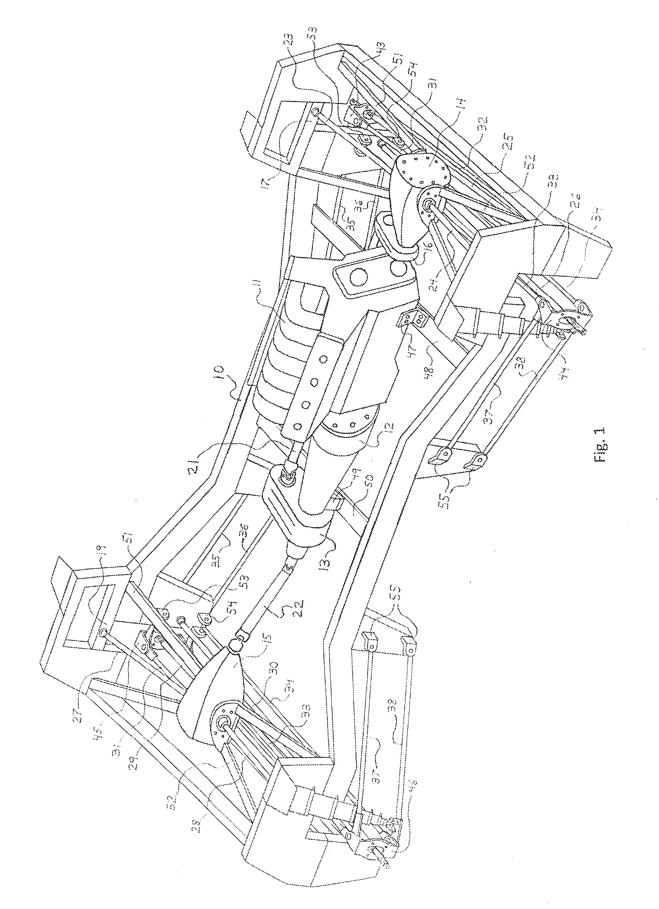
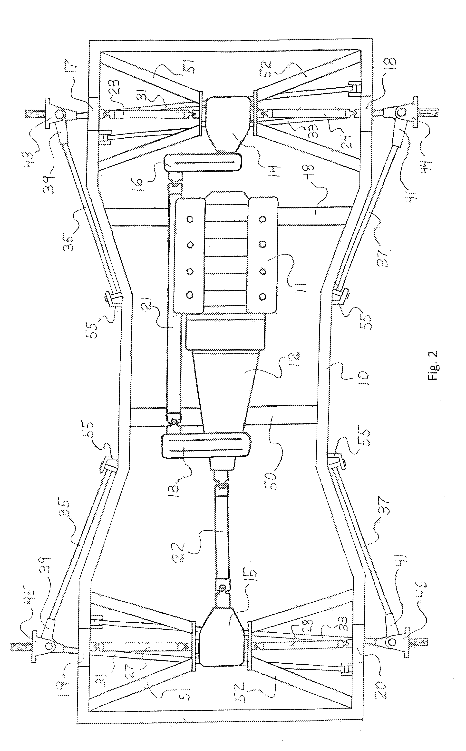
[0085]The present invention is directed to a drivetrain which is operably installed with the front and rear independent suspension systems disclosed in U.S. patent application Ser. No. 14 / 059,062, each suspension system based on a type of double wishbone configuration per wheel. The drivetrain includes means for receiving power at one frame side and then delivering that power to the wheel opposite the one frame side, this means accomplished via a unique gearbox known as a reverse power coupler.

[0086]Referring now to the drawings, a drivetrain for a four-wheel drive vehicle is schematically shown installed within a frame 10 and interactively associated with a powertrain. The drivetrain includes the front and rear differential housings 14 and 15, offset power coupler 16, and front and rear driver and passenger reverse power couplers 17 and 18, and 19 and 20, respectively; and the powertrain includes an engine 11, transmission 12, and transfer case 13. The means for transmitting power ...


PUM


Abstract

Disclosed herein is a novel drivetrain concept developed for the four wheel drive vehicle. This drivetrain is specifically designed to operate in conjunction with the extreme-travel independent suspension system, an independent suspension system that is disclosed in the U.S. patent application, Ser. No. 14 / 059,062; whereby, the criterion of this drivetrain design is dictated by the unique suspension configuration of the leading links. Inspired by Ford's twin-traction beam front suspension system, a key component of the drivetrain concept is a unique frame-mounted reverse power coupler, other components including a differential-mounted offset power coupler and differential housing assemblies. The drivetrain concept embraces the suspension system's fundamental properties-handling quality like an independent suspension system and travel and articulation capabilities potentially superior to that of a solid axle—by securing all weight-bearing components directly or indirectly to the frame and utilizing long axle shafts whose joints coincide with those of the leading links.

Description

CROSS-REFERENCE TO RELATED APPLICATIONS[0001]This application represents a novel drivetrain specifically designed to operate in conjunction with the extreme-travel Independent suspension system. This novel suspension system is covered in U.S. patent application Ser. No. 14 / 059,062.STATEMENT REGARDING FEDERALLY SPONSORED RESEARCH OR DEVELOPMENT[0002]Not ApplicableREFERENCE TO SEQUENCE LISTING, A TABLE, OR A COMPUTER PROGRAM LISTING COMPACT DISC APPENDIX[0003]Not ApplicableBACKGROUND OF THE INVENTION[0004]Four wheel drive (4WD) vehicles possessing independent suspension systems employ a drivetrain whose differential housings are mounted to the frame, the lone exception being the twin-traction beam front suspension system (TTB) developed by the Ford Motor Company. The differential housing is a component of the differential housing assembly whereby other components of the assembly include the bracketry that attaches the differential housing to the frame. Dimensionally, the side of the b...

Claims


Application Information

Patent Timeline
IPC IPC(8): B60K17/22B60G7/02B60K5/02B60K17/344B60K17/16
CPCB60K17/22B60K17/344B60G7/02B60K5/02B60K17/165B60G3/20B60G3/202B60G2200/18B60G2200/182B60G2300/07B60K5/1216B60K2005/003
Inventor BANDY, RONALD SCOTT
Owner BANDY RONALD SCOTT
Learn More