
Systems and methods to visualize component health and preventive maintenance needs for subsea control subsystem components

a subsystem and component health technology, applied in the field of subsea control subsystem management, can solve the problems of no high-quality tool to visualize physical subsea control system components and record, and achieve the effects of enhancing component health, reducing non-productive time, and high quality

Active Publication Date: 2015-07-02
HYDRIL USA DISTRIBUTION LLC
View PDF14 Cites 31 Cited by
  • Summary
  • Abstract
  • Description
  • Claims
  • Application Information

AI Technical Summary

Benefits of technology

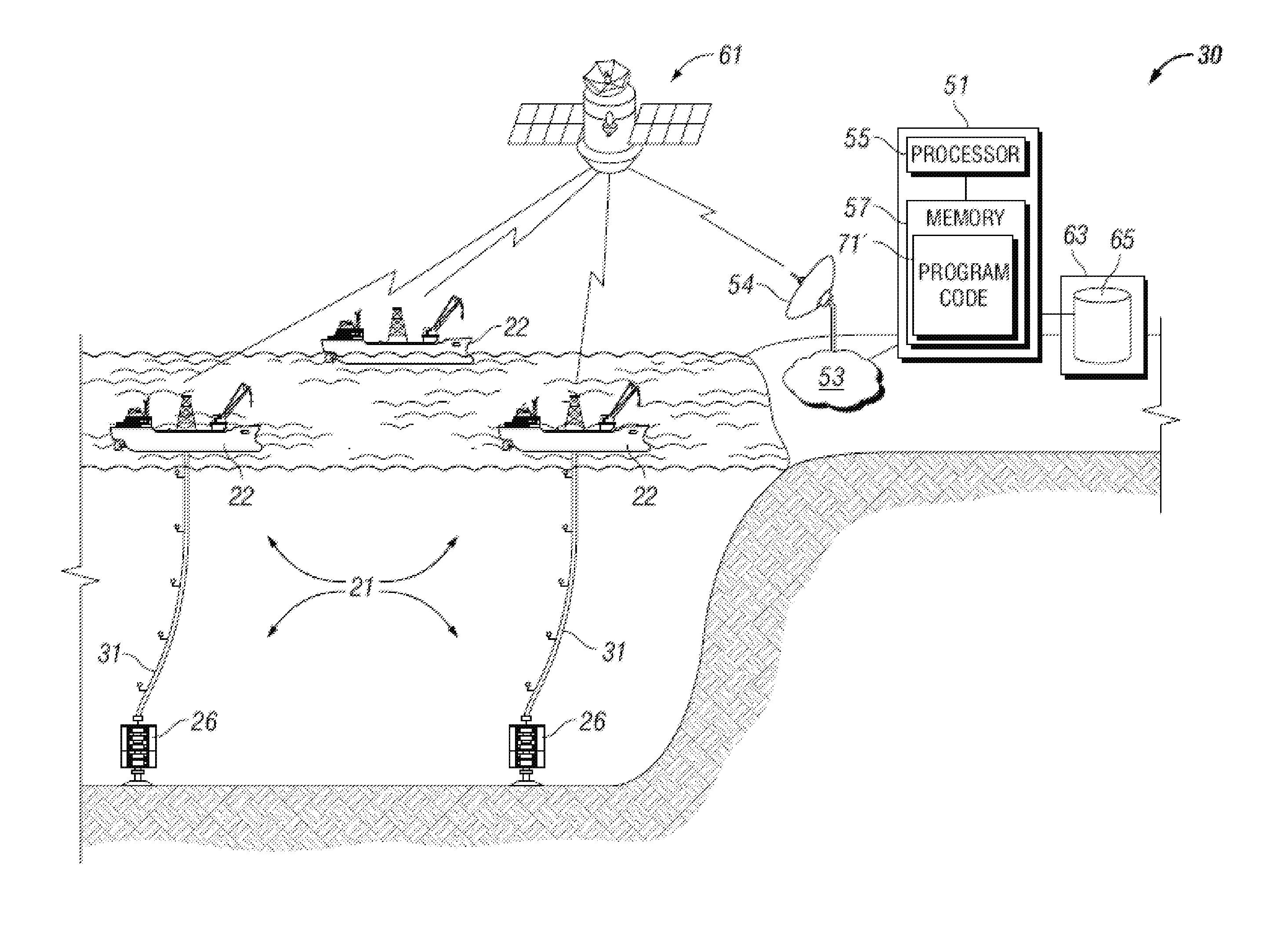
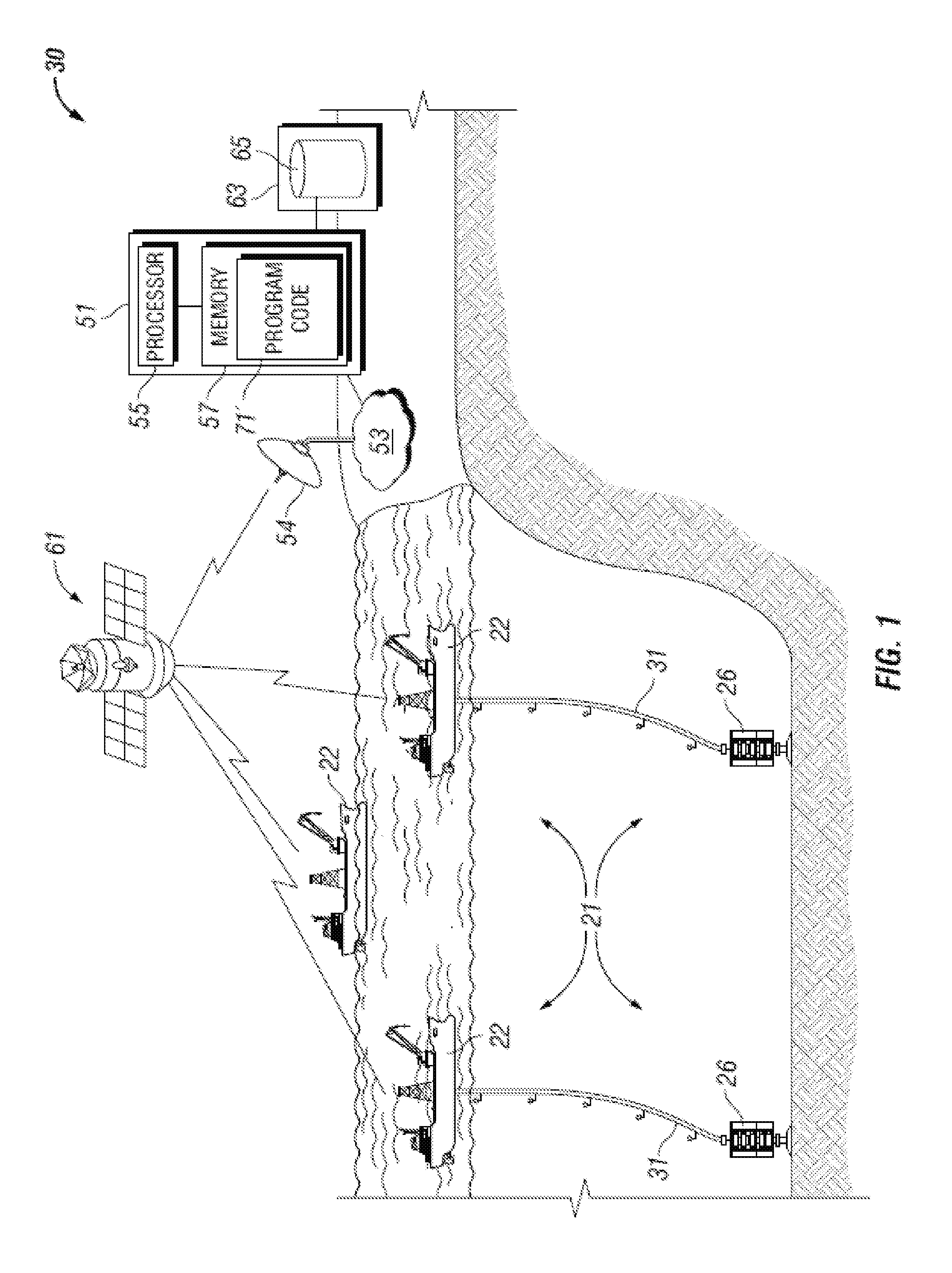
The patent text describes a system, method, and computer program for visualizing and analyzing the health of components in a subsea control system. The system can detect and count the usage cycles of components, track abnormal readings, and provide information about potential maintenance needs. It can also help customers identify and fix problems more quickly by providing remote visibility and converting existing data into actionable advice. The system collects data from key components, such as hydraulic components, to accurately calculate maintenance needs. The web-based solution provides a convenient way for onshore engineers to troubleshoot and optimize maintenance of the subsea control system. Overall, the invention addresses the need for better visualization and analysis of subsea control system components.

Problems solved by technology

Recognized by the Applicant, however, is that there is no high-quality tool to visualize physical subsea control system components and record usage data of those components by the drilling control system in terms of counting cycles from the time of installation of a component, trending “normal” operational readings from the components after installation, or other data reporting that would aid a customer in identifying deviations from normal operating conditions.

Method used


Image

  • Systems and methods to visualize component health and preventive maintenance needs for subsea control subsystem components
  • Systems and methods to visualize component health and preventive maintenance needs for subsea control subsystem components
  • Systems and methods to visualize component health and preventive maintenance needs for subsea control subsystem components

Examples


Embodiment Construction

[0043]The present invention will now be described more fully hereinafter with reference to the accompanying drawings, which illustrate embodiments of the invention. This invention, however, may be embodied in many different forms and should not be construed as limited to the illustrated embodiments set forth herein. Rather, these embodiments are provided so that this disclosure will be thorough and complete, and will fully convey the scope of the invention to those skilled in the art. Like numbers refer to like elements throughout. Prime notation, if used, indicates similar elements in alternative embodiments.

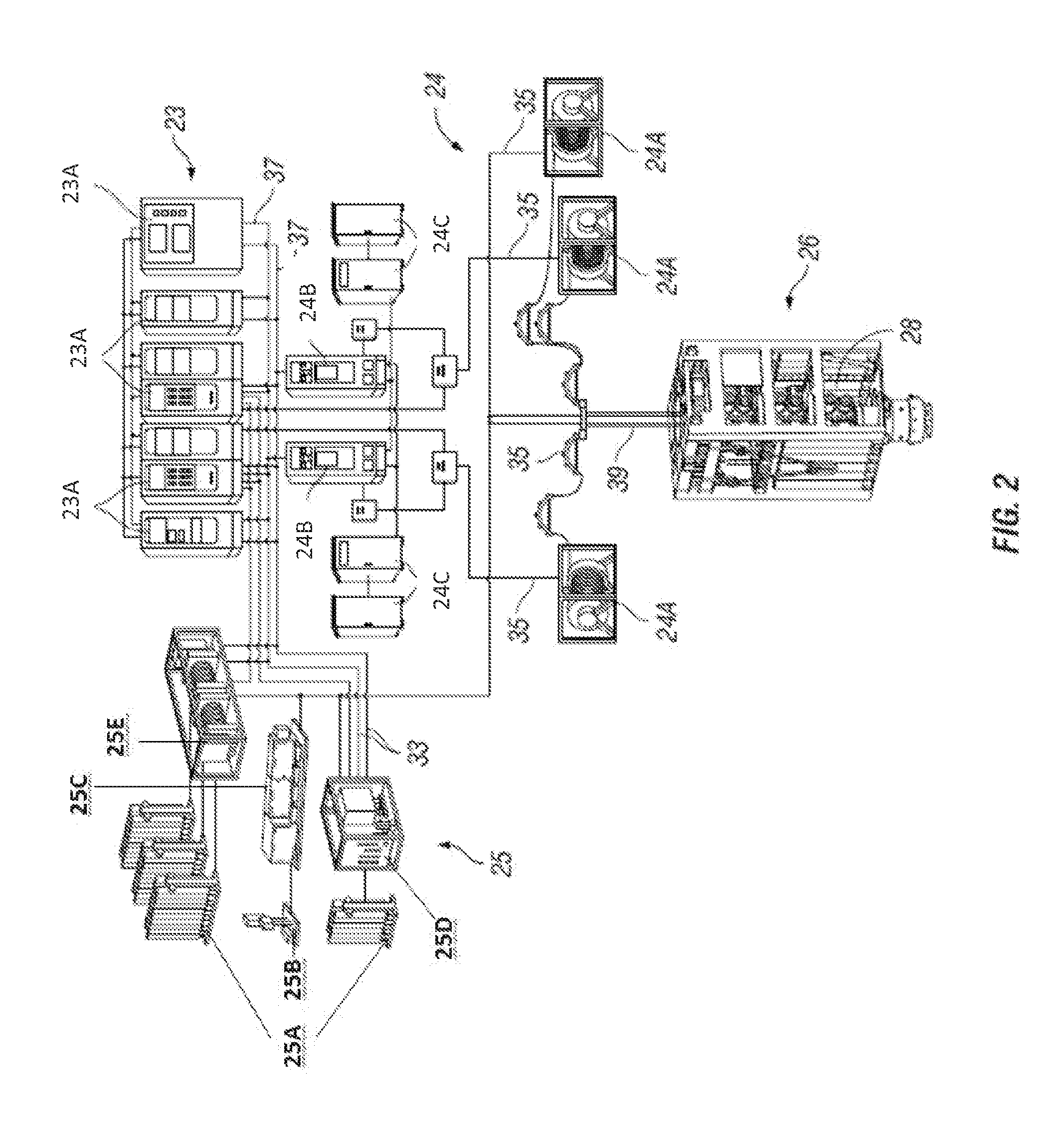
[0044]Various embodiments or the invention provide an integrated platform that provides a robust user interface, which allows the user to view the data contents of the drilling control system data logger in a user-friendly manner to provide diagnostic and maintenance tools to assess the performance and health of drilling system components, and enable transmission of the data, r...


PUM


Abstract

Systems and methods to visualize component health and preventive maintenance needs for subsea control subsystem components are provided. Embodiments can include energizing one or more solenoids, detecting a solenoid firing event, detecting activity in blowout preventer components downchain from the solenoids, and incrementing a cycle count for the one or more solenoids and each downchain blowout preventer component activated. Embodiments can include projecting a replacement date for the solenoid or any of the downchain blowout preventer components based on the cycle count and user-defined thresholds. In embodiments, a user is provided with an interactive graphical representation of a blowout preventer including selectable blowout preventer components thereby to visualize component health and preventive maintenance needs.

Description

RELATED APPLICATIONS[0001]The present application is a non-provisional application which claims priority to and the benefit of U.S. Provisional Application No. 61 / 923,076, filed on Jan. 2, 2014 and titled “Systems, Computer Programs, and Methods of Providing Data Visualization for Health Monitoring and Preventive Maintenance Decision-Making for Subsea Control Subsystem Components,” the disclosure of which is incorporated herein in its entirety.BACKGROUND OF THE INVENTION[0002]1. Field of the Invention[0003]This invention relates generally to subsea control subsystem management, and in particular to the health and maintenance of control subsystem components.[0004]2. Description of the Related Art[0005]Conventional drilling control system design allows data collection on a drilling rig. Current drilling control systems are capable of communicating remotely from a central location to rigs enabled with a remote services network. Generally, this network is primarily used to manage limite...

Claims


Application Information

Patent Timeline
Patent Type & Authority Applications(United States)
IPC IPC(8): E21B47/12E21B34/04
CPCE21B34/045E21B47/12E21B33/0355E21B34/16E21B41/0007E21B44/00E21B47/001
Inventor PANICKER-SHAH, KALPANA
Owner HYDRIL USA DISTRIBUTION LLC
Learn More