Holographic imaging element operable to generate multiple different images of an object

a technology of holographic imaging and image, applied in the field of holographic imaging elements, can solve the problems of wavelength dependence and may be less efficient than conventional lenses, and achieve the effect of improving the sensitivity and versatility of microscopes

Inactive Publication Date: 2015-07-02
RGT UNIV OF CALIFORNIA
View PDF9 Cites 4 Cited by
  • Summary
  • Abstract
  • Description
  • Claims
  • Application Information

AI Technical Summary

Benefits of technology

[0009]In some embodiments, a hybrid zone plate holographically combines the features of two zone plates with different pupil properties, enabling the simultaneous collection of bright field and dark field images. Although the image intensity of each of the images is reduced as the beam is divided, this advance can improve the sensitivity and versatility of microscopes, which typically operate in one mode or the other. Short-wavelength microscopes, which often use one mode or the other, may use both imaging modes simultaneously. In some embodiments, a hybrid zone plate has the potential to utilize a large detector area, which may include unused, out of focus portions of the field of view due to a tilted focal plane in an off-axis geometry.

Problems solved by technology

Holographic lenses, however, have a wavelength-dependence and may be less efficient than conventional lenses.

Method used


Image

  • Holographic imaging element operable to generate multiple different images of an object
  • Holographic imaging element operable to generate multiple different images of an object
  • Holographic imaging element operable to generate multiple different images of an object

Examples


example 1

[0071]A hybrid zone plate for mask blank inspection using the Actinic Inspection Tool (AIT) at Lawrence Berkeley National Laboratory is described below. The AIT is an EUV (13 nm wavelength) photomask microscope that operates at the Advanced Light Source at Lawrence Berkeley National Laboratory and uses a zone plate as a high-magnification objective lens. One function of a hybrid zone plate described below is to image defects using bright field imaging and dark field imaging simultaneously with the charge-coupled device (CCD) camera geometry used in the AIT. Previous investigations have shown the importance of both bright field and dark field imaging in the detection of amplitude defects and phase defects on EUV masks. Pairing these two modes of operation, however, has been a challenging aspect of system design, and most planned or operating systems choose one mode or the other. With a hybrid zone plate, both modes are used simultaneously, enhancing the potential defect detection sen...

example 2

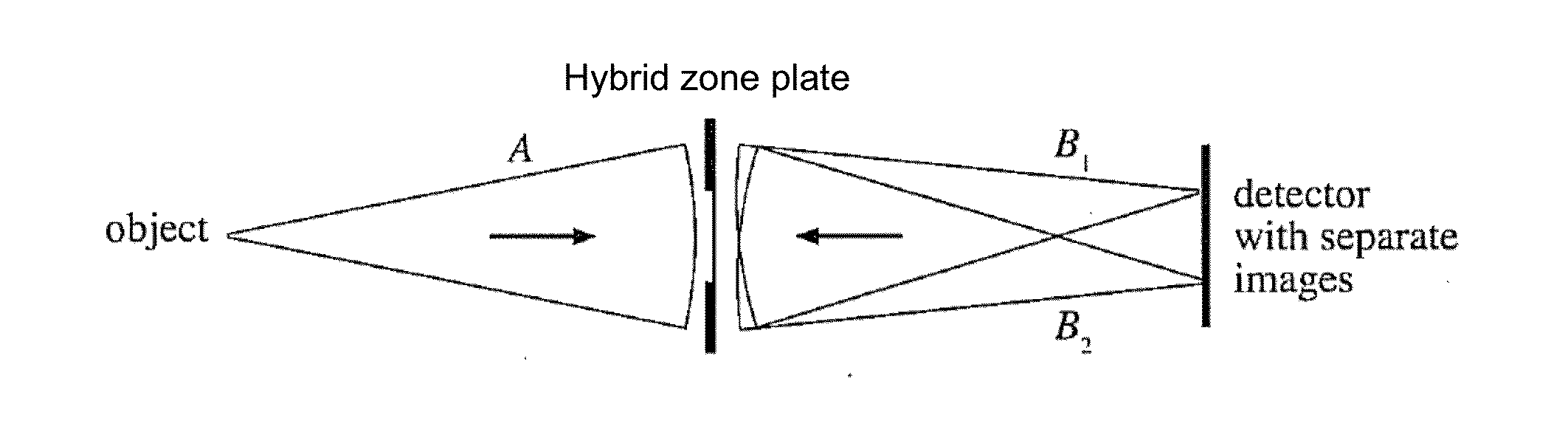
[0091]A hybrid zone plate for EUV mask blank inspection using the AIT at Lawrence Berkeley National Laboratory is described below. One function of the hybrid zone plate described below is to simultaneously project multiple images of a single object on a detector in such a way that each image contains different information. The images can be analyzed either as a group or individually.

[0092]For the AIT in particular, one limitation of the through-focus data series quality comes from illumination non-uniformities. As the mask is moved longitudinally (through focus), the mask position within the illumination pattern shifts, changing the illumination in the vicinity of the features being imaged. This issue may be addressed by introducing a hybrid zone plate that replaces the zone plate.

[0093]In general, given a known illumination pattern, a holographic lens can be designed to project nearly arbitrary fields onto a detector. The zone plate is one simple case of how a holographic lens can ...


PUM


Abstract

This disclosure provides systems, methods, and apparatus related to imaging elements. In one aspect, a system includes an electromagnetic radiation source, a detector, and an imaging element. The electromagnetic radiation source is configured to generate electromagnetic radiation. The imaging element is configured to simultaneously project a plurality of images of an object onto the detector after the electromagnetic radiation interacts with the object. Each of the plurality of images of the object has different properties from others of the plurality of images.

Description

RELATED APPLICATIONS[0001]This application is a continuation of International Application No. PCT / US2013 / 056644, filed Aug. 26, 2013, which claims priority to U.S. Provisional Patent Application No. 61 / 695,933, filed Aug. 31, 2012, both of which are herein incorporated by reference. This application is related to U.S. Pat. No. 6,963,395, which is herein incorporated by reference.STATEMENT OF GOVERNMENT SUPPORT[0002]This invention was made with government support under Contract No. DE-AC02-05CH11231 awarded by the U.S. Department of Energy. The government has certain rights in this invention.TECHNICAL FIELD[0003]This disclosure relates generally to imaging elements, and more particularly to holographic imaging elements, hybrid lenses, and hybrid zone plates.BACKGROUND[0004]An example of a conventional refractive lens is an optical device which transmits light and refracts light, and may converge of diverge a light beam, depending on its configuration. Conventional lenses also include...

Claims


Application Information

Patent Timeline
Patent Type & Authority Applications(United States)
IPC IPC(8): G02B27/10G02B5/18G02B5/32
CPCG02B27/1013G02B27/1086G02B5/1895G02B5/32G02B7/38G03H1/08G03H1/30G02B27/0075G02B5/1819G02B5/1823
Inventor GOLDBERG, KENNETH A.MOCHI, IACOPO
Owner RGT UNIV OF CALIFORNIA
Why Eureka
Try Eureka