
Methods and systems for subsea direct current power distribution

a technology of direct current and subsea power, applied in the field of system and method of subsea high-voltage direct current (hvdc) transmission and distribution, can solve the problems of increasing system cost, increasing weight, and affecting the efficiency of transmission and distribution systems

Active Publication Date: 2015-07-02
GENERAL ELECTRIC CO
View PDF2 Cites 11 Cited by
  • Summary
  • Abstract
  • Description
  • Claims
  • Application Information

AI Technical Summary

Benefits of technology

The patent describes a submersible power system that includes a DC power source, a submersible power distribution system, and a switchyard module. The power distribution system has multiple power conversion modules that are removably positioned in a receptacle. The switchyard module has multiple switches that isolate and bypass each power conversion module from the DC power source. The system also includes a floating recovery platform for positioning and lifting the power conversion modules. The technical effects of this system include the ability to safely and efficiently distribute power in an underwater environment and the ability to easily recover and maintain the power conversion modules.

Problems solved by technology

As such, some known subsea oil and gas production systems are electric power intensive, and a robust, sturdy, and reliable electrical transmission and distribution (T&D) is required.
Such AC transmission and distribution systems face technical challenges, which become more significant, e.g., when the transmission distance is in excess of one hundred kilometers.
For example, the significant reactive power drawn from the distributed subsea cable capacitance restrains the power delivery capability as well as increases the system cost.
Further, as pump, motor, and distribution components increase in power and size, the weight increases.
Moreover, the electrical connections between components in subsea distribution systems typically require wet-mateable connectors, which are significantly more expensive than dry-mateable connectors.
Furthermore, wet-mateable subsea DC connectors that can withstand high voltage, e. g., 50 kiloVolts (kV) DC or higher, if commercially available, would require a complex and costly design.
Moreover, due to the inaccessibility of the components within the enclosures, maintenance on any one component within the enclosure typically requires completely removing the T&D system from service and raising the unitary enclosure from its subsea location onto a ship or other platform.

Method used


Image

  • Methods and systems for subsea direct current power distribution
  • Methods and systems for subsea direct current power distribution
  • Methods and systems for subsea direct current power distribution

Examples


Embodiment Construction

[0024]In the following specification and the claims, reference will be made to a number of terms, which shall be defined to have the following meanings

[0025]The singular forms “a”, “an”, and “the” include plural references unless the context clearly dictates otherwise.

[0026]“Optional” or “optionally” means that the subsequently described event or circumstance may or may not occur, and that the description includes instances where the event occurs and instances where it does not.

[0027]Approximating language, as used herein throughout the specification and claims, may be applied to modify any quantitative representation that could permissibly vary without resulting in a change in the basic function to which it is related. Accordingly, a value modified by a term or terms, such as “about” and “substantially”, are not to be limited to the precise value specified. In at least some instances, the approximating language may correspond to the precision of an instrument for measuring the valu...


PUM

PropertyMeasurementUnit
lengthaaaaaaaaaa
water depthsaaaaaaaaaa

Abstract

A submersible power system includes at least one DC power source and at least one submersible power distribution system electrically coupled to the at least one DC power source. The at least one submersible power distribution system includes at least one receptacle configured to be exposed to an underwater environment. The at least one submersible power distribution system also includes a plurality of power conversion modules removably positioned within the at least one receptacle. Each power conversion module of the plurality of power conversion modules includes an enclosure configured to be exposed to the underwater environment. The at least one submersible power distribution system further includes at least one switchyard module selectably coupled to and uncoupled from the plurality of power conversion modules. The at least one switchyard module includes a plurality of switches configured to electrically bypass and isolate each power conversion module from the DC power source.

Description

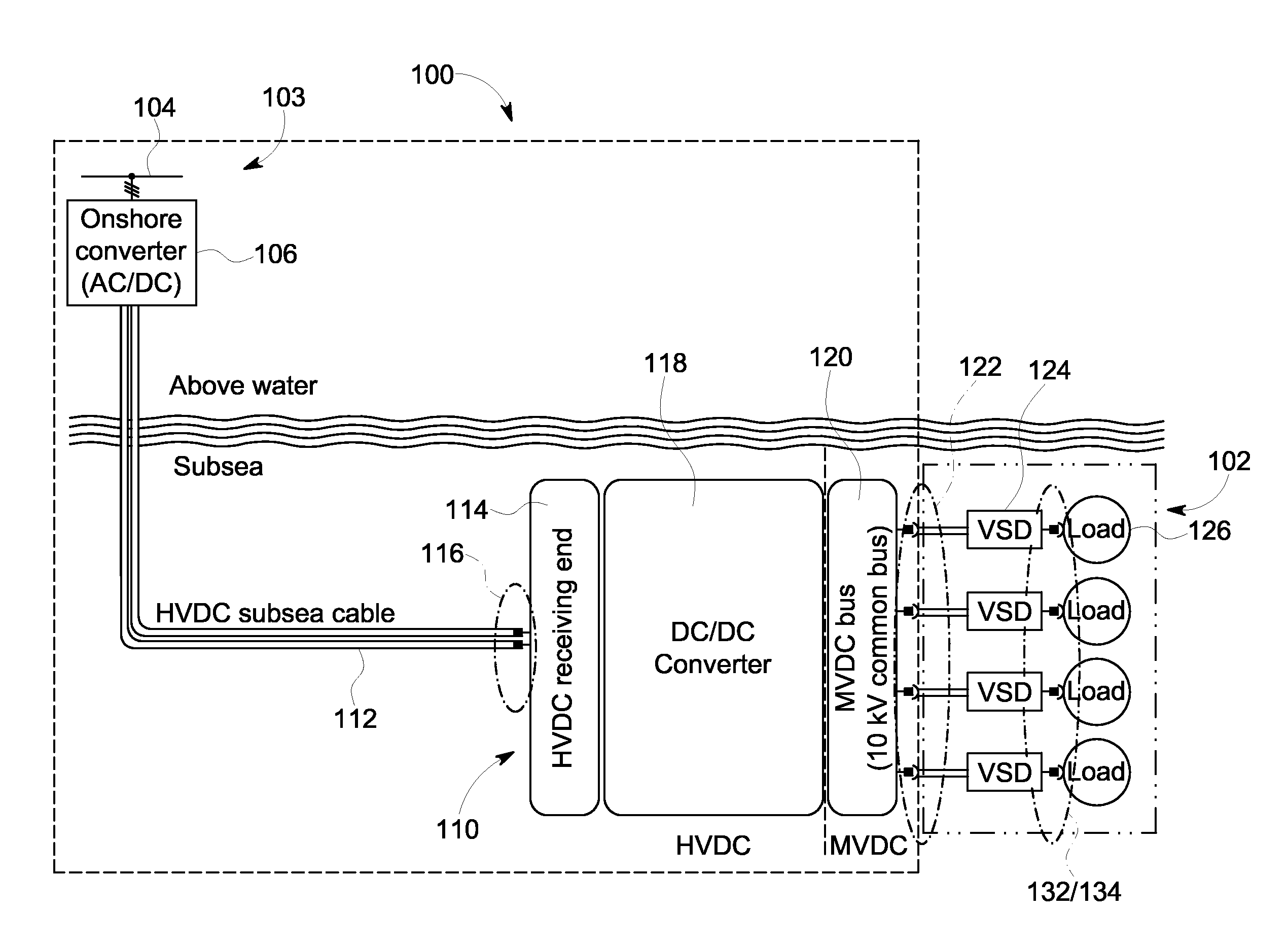
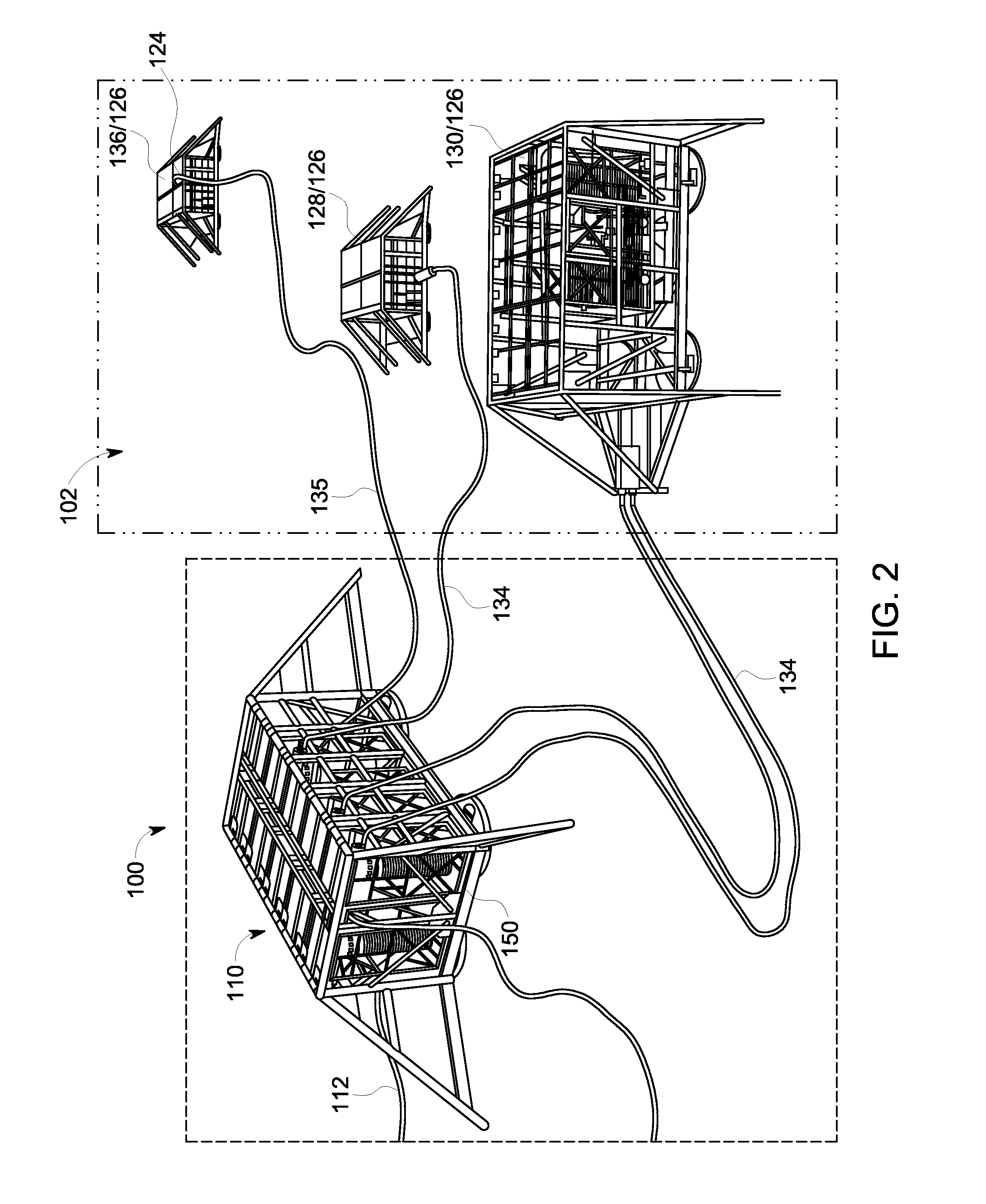
BACKGROUND[0001]This description relates to power transmission and distribution, and, more particularly, to systems and methods for subsea high-voltage direct current (HVDC) transmission and distribution.[0002]As oil and gas fields in shallow waters diminish, e.g., water depths less than approximately 500 meters (m) (1640 feet (ft.)), producers are tapping offshore fields in deeper waters, e.g., water depths of 500 m (1640 ft.) and greater. Such deep water fields not only include oil and gas production installations that operate far below the surface of the sea, but, also far away from the shore, e.g., greater than approximately 300 kilometers (km) (186 miles (mi)).[0003]In many known subsea oil and gas production systems, typical equipment for such subsea oil and gas recovery and production includes gas compressors and pumps. Electric variable speed drive (VSD) and motor systems are one way to directly power such equipment in deep water environments. Reliable delivery of electric p...

Claims


Application Information

Patent Timeline
Patent Type & Authority Applications(United States)
IPC IPC(8): H02J1/10H02B1/24H02B7/00
CPCH02J1/10H02B1/24H02B7/00H02J1/08H02J1/102H02J3/36H02J4/00E21B41/08E21B43/017Y02E60/60Y10T29/49002H02J1/002H02J2310/12
Inventor HYTTEN, NICOLAIWIJEKOON, PINIWAN THIWANKA BANDARAPOULIQUEN, JEAN-LOUISBAERD, HENRISIHLER, CHRISTOF MARTIN
Owner GENERAL ELECTRIC CO
Learn More