Unidirectional condenser microphone unit

a condenser microphone and microphone technology, applied in the direction of piezoelectric/electrostrictive transducers, mouthpiece/microphone attachments, transducer types, etc., can solve the problem of insufficient equivalent circuits of lumped constant, and achieve high acoustic resistance, prevent discontinuous connection, and prevent the effect of diaphragm drive force decreas

Inactive Publication Date: 2015-07-02
AUDIO-TECHNICA
View PDF4 Cites 6 Cited by
  • Summary
  • Abstract
  • Description
  • Claims
  • Application Information

AI Technical Summary

Benefits of technology

[0026]According to the present invention, the sealing member forms the acoustic distributed constant circuit including: the first portion in which the cross-sectional area of the sound path continuously increases, the sound path running from the acoustic resistance part behind the fixed pole of the electroacoustic transducer to reach the rear acoustic terminal through the air chamber; and the second portion on the rear acoustic terminal side in which the cross-sectional area continuously decreases toward the direction farther from the sound pickup source. The first portion of these portions operates as a horn-speaker-like acoustic transducer. This can prevent discontinuous connection between the acoustic impedance with a high acoustic resistance and the air impedance in free space.
[0027]Moreover, the rear acoustic terminal has acoustic mass, and the second portion on the rear acoustic terminal side in which the cross-sectional area continuously decreases toward the direction farther from the sound pickup source adds acoustic mass to the rear acoustic terminal in the high tone range. Hence, entrance of sound waves into the rear acoustic terminal is restricted in the high tone range. This can prevent a decrease in diaphragm drive force at a frequency at which a half wavelength ½λ of a sound wave is equal to the distance between the acoustic terminals of the electroacoustic transducer. Moreover, the acoustic mass on the rear acoustic terminal side increases with distance from the sound pickup source. Hence, resonance with an acoustic capacitance existing in the air chamber for obtaining non-directional components is reduced.

Problems solved by technology

In the case of a high frequency of around 10 kHz, however, acoustic elements approach the wavelengths of sound waves, and hence the lumped constant equivalent circuits are insufficient.

Method used


Image

  • Unidirectional condenser microphone unit
  • Unidirectional condenser microphone unit
  • Unidirectional condenser microphone unit

Examples


Embodiment Construction

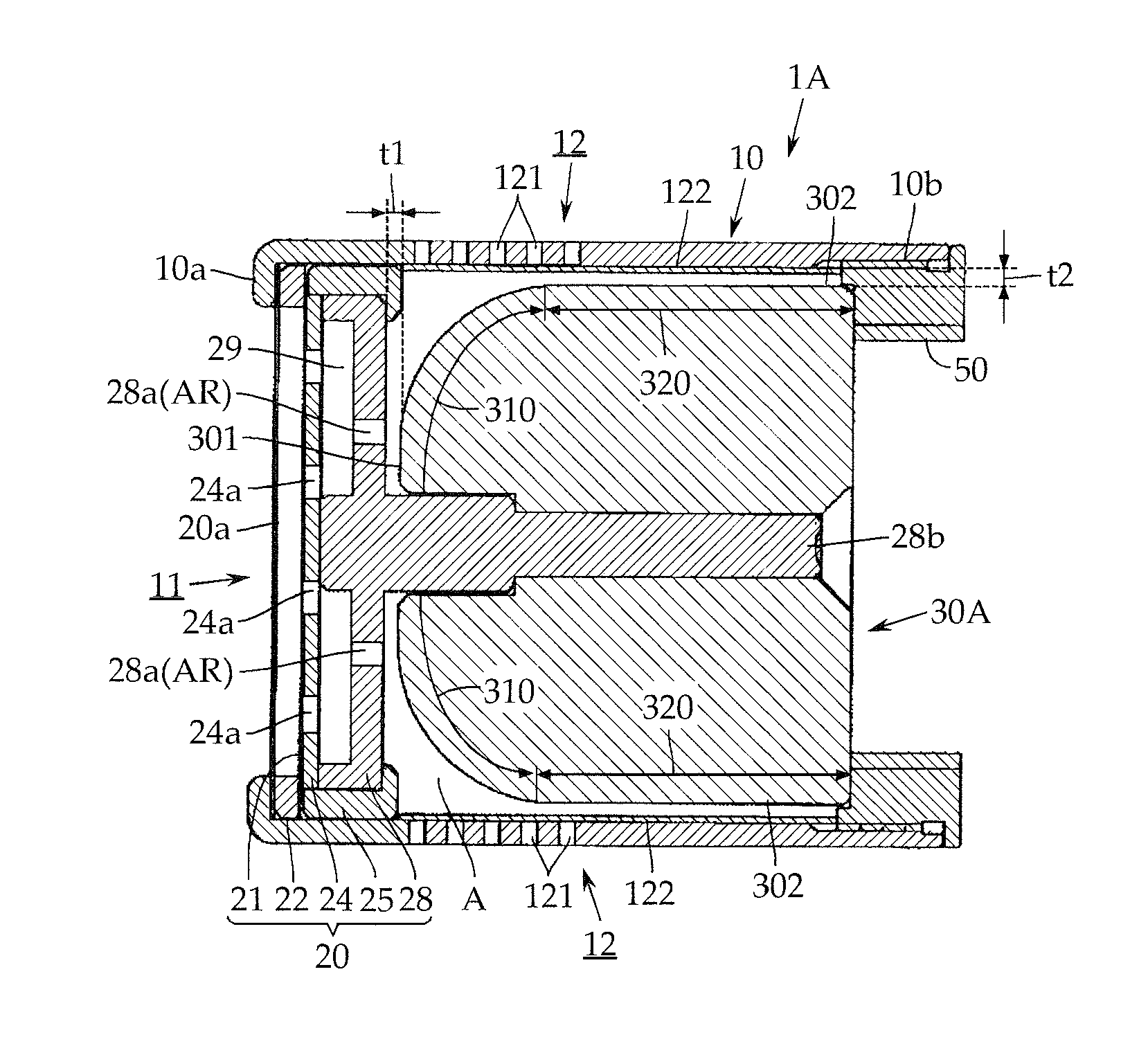
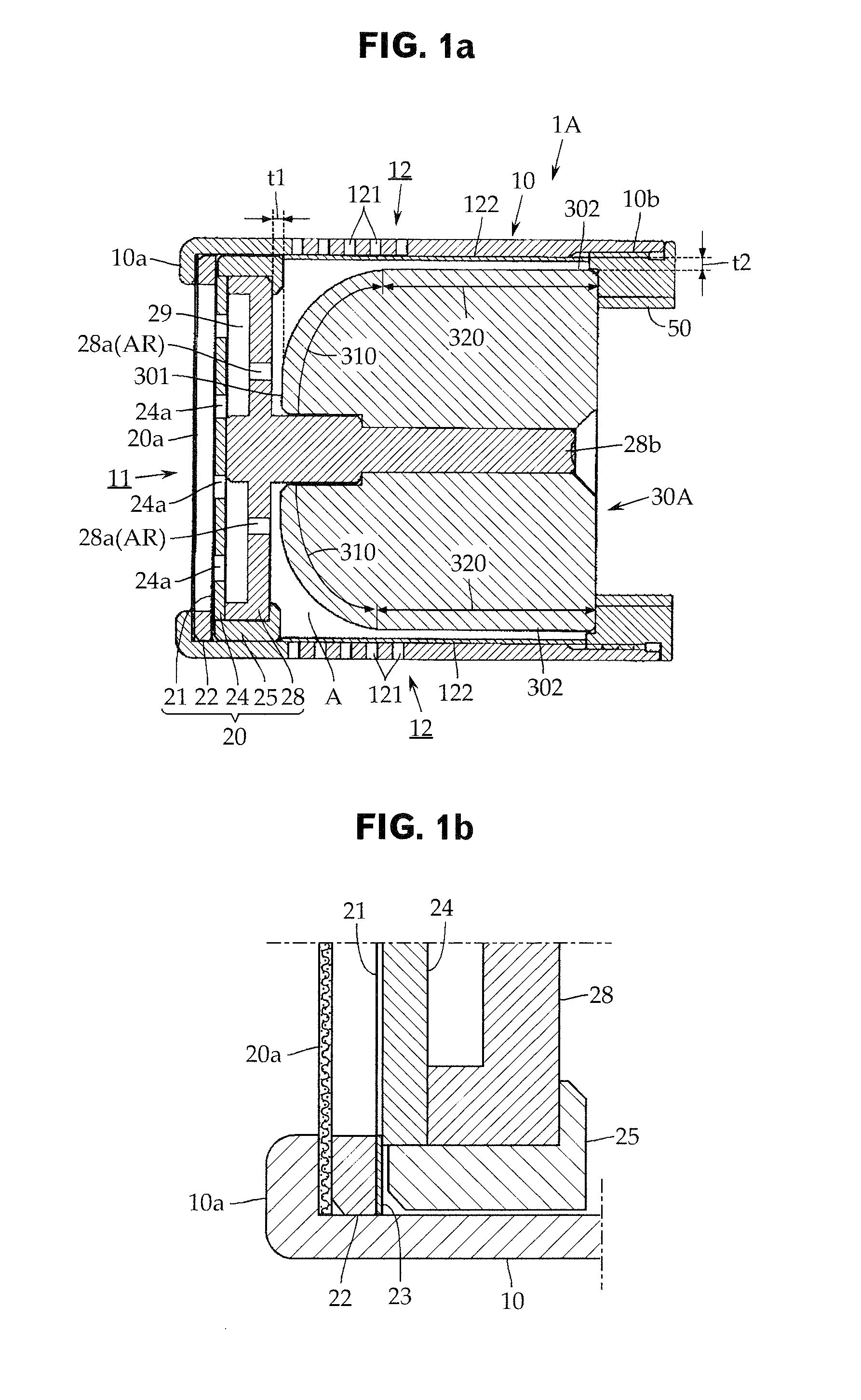
[0035]Next, an embodiment of the present invention is described with reference to FIGS. 1 to FIGS. 3, and the present invention is not limited to the embodiment. Note that, in describing the present embodiment, substantially the same components as those in the microphone unit 1B according to the conventional technique that is described in BACKGROUND ART with reference to FIG. 4 are denoted by the same reference signs as those in the microphone unit 1B.

[0036]With reference to FIG. 1A, a unidirectional condenser microphone unit (hereinafter, simply referred to as “microphone unit” in some cases) 1A according to the present embodiment includes, as a basic configuration, a unit case 10, an electrostatic type electroacoustic transducer 20, and a sealing member 30A.

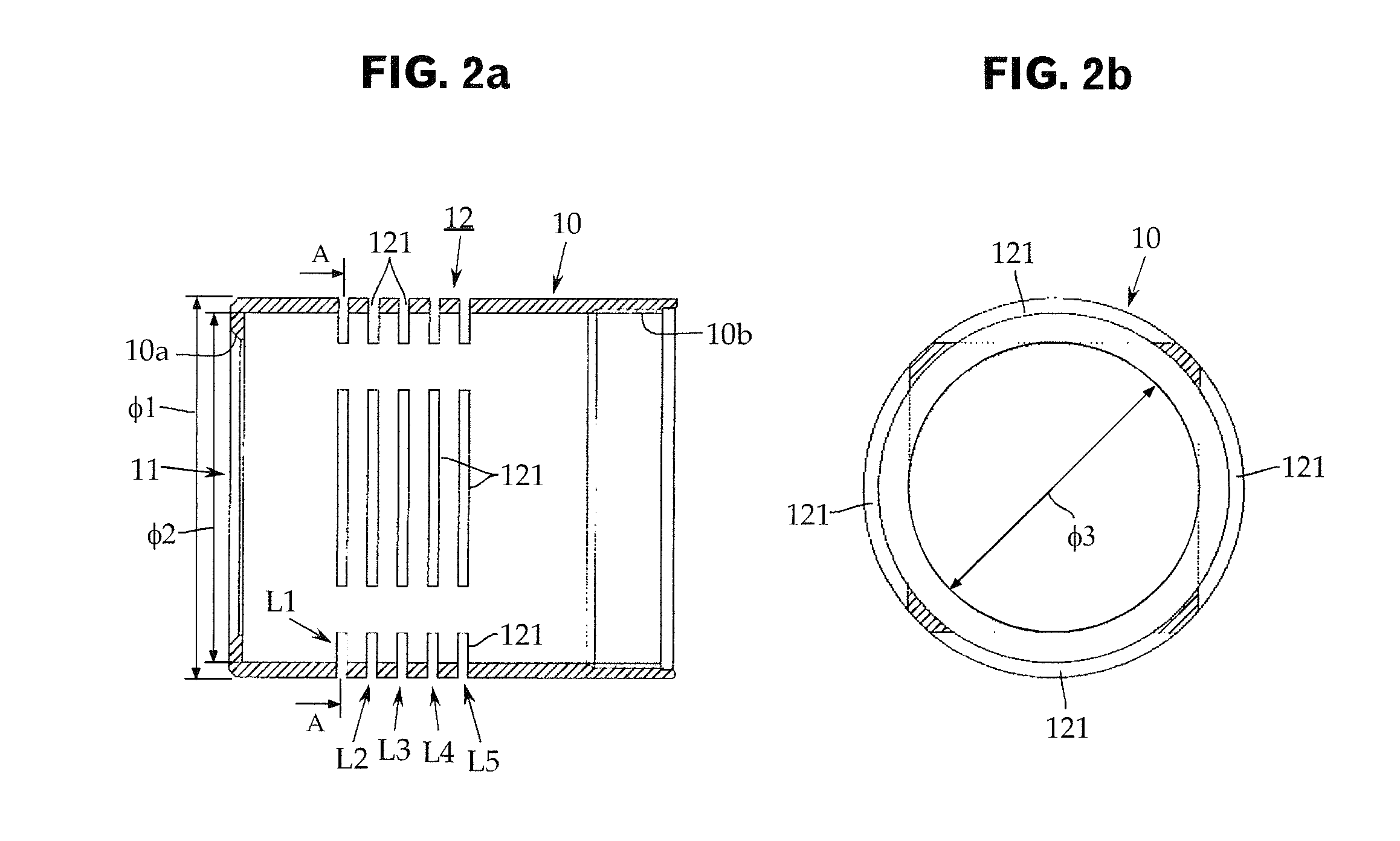
[0037]The unit case 10 is a cylindrical member made of an electrically conductive material such as aluminum and a brass alloy, and one end (the left end inFIGS. 1) thereof is opened as a front acoustic terminal 11. Similarly to...


PUM


Abstract

An acoustic impedance on a rear acoustic terminal side is set such that satisfactory directionality is obtained even in a high tone range. A rear portion of a sealing member 30A fitted to a unit case 10 is formed in a convex spherical shape, ranging from an apex part 301 to a hem part 302. The sealing member 30A forms an acoustic distributed constant circuit including: a first portion 310 in which a cross-sectional area of a sound path continuously increases, the sound path running from acoustic resistance parts AR as sound holes 28a of an electroacoustic transducer 20 to reach a rear acoustic terminal 12 through an air chamber A; and a second portion 320 on the rear acoustic terminal 12 side in which a cross-sectional area continuously decreases toward a direction farther from a sound pickup source.

Description

CROSS-REFERENCE TO RELATED APPLICATION[0001]The present application is based on, and claims priority from, Japanese Application Serial Number JP2013-268351, filed Dec. 26, 2013, the disclosure of which is hereby incorporated by reference herein in its entirety.TECHNICAL FIELD[0002]The present invention relates to a unidirectional condenser microphone unit, and, more specifically, to a technique of setting an acoustic impedance on a rear acoustic terminal side so as to obtain satisfactory directionality even in a high tone range.BACKGROUND ART[0003]In an end-address microphone (a rod-shaped microphone that picks up sound waves from its one end), a rear acoustic terminal is made by forming an opening in a peripheral wall portion of a cylindrical unit case. An example (see, for example, Japanese Patent Application Publication No. 2011-009807) of the conventional technique is described with reference to FIG. 4.[0004]A unidirectional condenser microphone unit (hereinafter, simply referre...

Claims


Application Information

Patent Timeline
Patent Type & Authority Applications(United States)
IPC IPC(8): H04R1/08
CPCH04R1/08H04R19/04
Inventor AKINO, HIROSHI
Owner AUDIO-TECHNICA
Why Eureka
Try Eureka