
Methods and apparatuses for producing laminated glass sheets

a technology of laminated glass and methods, applied in glass making apparatus, glass rolling apparatus, manufacturing tools, etc., can solve the problems of increased production costs, glass articles incorporated in these devices may be susceptible to damage, and glass articles damaged

Active Publication Date: 2015-07-09
CORNING INC
View PDF9 Cites 6 Cited by
  • Summary
  • Abstract
  • Description
  • Claims
  • Application Information

AI Technical Summary

Benefits of technology

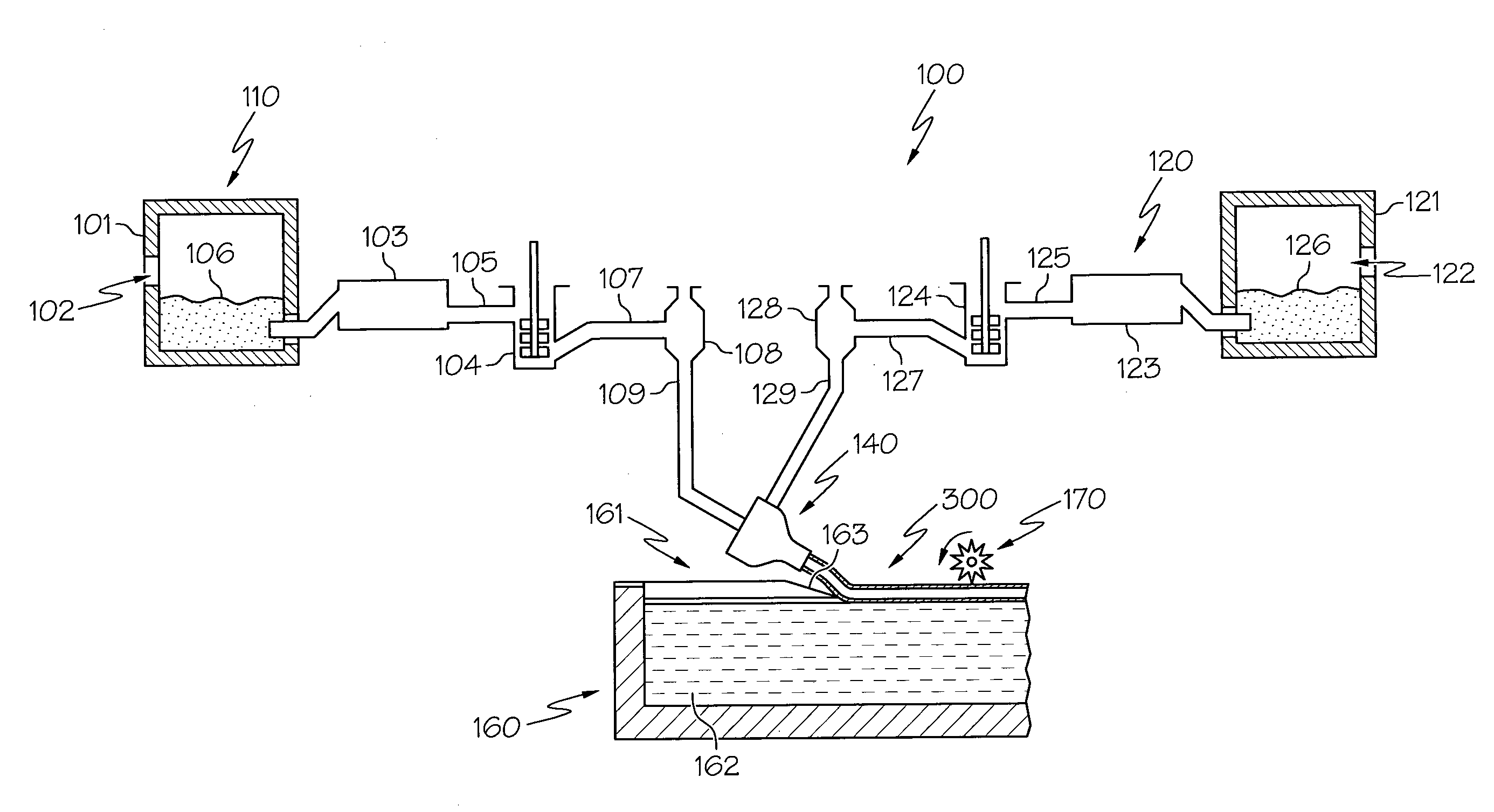
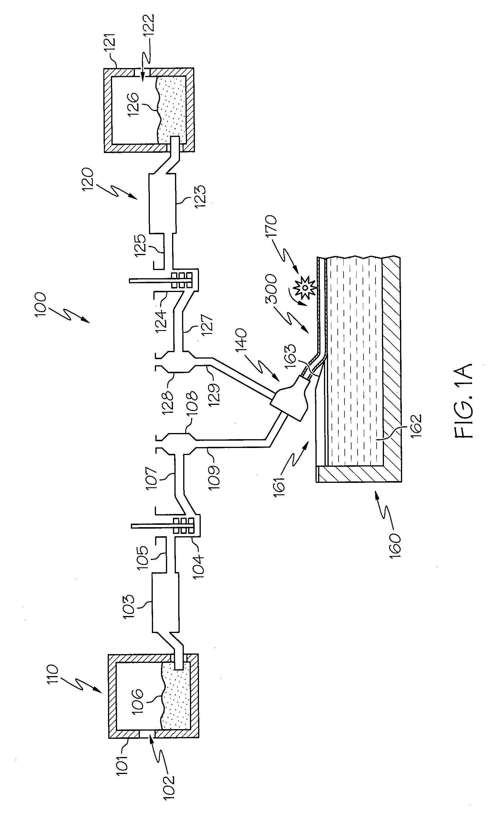
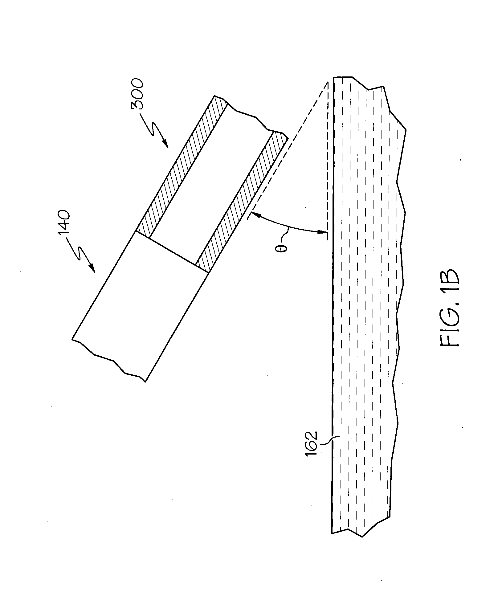
The patent describes methods and apparatus for making laminated glass sheets. The methods involve creating a multi-layer glass melt from a molten core glass and at least one molten cladding glass, and directing it onto the surface of a molten metal bath in a float tank. The width of the multi-layer glass melt is smaller than the width of the float tank before it enters the tank. The multi-layer glass melt flows over the surface of the molten metal bath and solidifies into a laminated glass sheet with a constant ratio of core to cladding thickness. The apparatus includes a slot draw apparatus with a core glass slot and at least one cladding glass slot, which are oriented in parallel with each other. The apparatus also includes a float tank containing a molten metal bath, with the slot draw apparatus positioned over it. The width of the slot draw apparatus is smaller than the width of the float tank. The methods and apparatus allow for the efficient production of laminated glass sheets.

Problems solved by technology

The glass articles incorporated in these devices may be susceptible to damage during transport and / or use of the associated device.
Chemical and thermal tempering processes may be used to strengthen a glass article after the article is formed, thereby requiring additional processing steps and handling of the glass article, both of which may result in damage to the glass article which increases production costs and decreases productivity, particularly for larger glass articles.

Method used


Image

  • Methods and apparatuses for producing laminated glass sheets
  • Methods and apparatuses for producing laminated glass sheets
  • Methods and apparatuses for producing laminated glass sheets

Examples


example 1

[0051]While not wishing to be bound by theory, it is believed that the methods and apparatuses described herein may be used to form laminated glass sheets as exemplified by the following hypothetical example. The hypothetical slot draw apparatus has a core slot disposed between a first cladding slot and a second cladding slot. The core slot had a height Hc of 0.0125 m. The cladding slots each had a height Hcla=Hclb=0.006 m. The hypothetical slot draw apparatus had a width Ws of 0.4 m. Based on the foregoing, the core to cladding ratio Tc:Tcl of the glass melt discharged from the slot draw apparatus is 4.5. In this hypothetical, the slot draw apparatus may be coupled to a core glass delivery system and a cladding glass delivery system which, combined, are capable of delivering 37 metric tons of glass per day to the slot draw apparatus. The core glass and the cladding glass compositions hypothetically have identical viscosities and the temperature of the glass manufacturing system is ...


PUM

PropertyMeasurementUnit
slot angleaaaaaaaaaa
receiving plane angleaaaaaaaaaa

Abstract

According to one embodiment, a method for forming a laminated glass sheet includes forming a multi-layer glass melt (300) from a molten core glass (106) and at least one molten cladding glass (126). The multi-layer glass melt (300) has a width Wm, a melt thickness Tm and a core to cladding thickness ratio TC:TCl. The multi-layer glass melt (300) is directed onto the surface of a molten metal bath (162) contained in a float tank (160). The width Wm of the multi-layer glass melt (300) is less than the width Wf of the float tank (160) prior to the multi-layer glass melt (300) entering the float tank (160). The multilayer glass melt (300) flows over the surface of the molten metal bath (162) such that the width Wm of the multi-layer glass melt (300) increases, the melt thickness Tm decreases, and the core to cladding thickness ratio TC:TCl remains constant as the multi-layer glass melt (300) solidifies into a laminated glass sheet. The invention also relates to the associated apparatus.

Description

BACKGROUND[0001]1. Field[0002]The present specification generally relates to laminated glass sheets and, more specifically, to methods and apparatuses for producing laminated glass sheets by float processes.[0003]2. Technical Background[0004]Glass articles, such as cover glasses, glass backplanes and the like, are employed in both consumer and commercial electronic devices such as LCD and LED displays, computer monitors, automated teller machines (ATMs) and the like. Some of these glass articles may include “touch” functionality which necessitates that the glass article be contacted by various objects including a user's fingers and / or stylus devices and, as such, the glass must be sufficiently robust to endure regular contact without damage. The glass articles incorporated in these devices may be susceptible to damage during transport and / or use of the associated device. Accordingly, glass articles used in such devices may require enhanced strength to be able to withstand not only r...

Claims


Application Information

Patent Timeline
Patent Type & Authority Applications(United States)
IPC IPC(8): C03B18/12C03B7/08
CPCC03B7/08C03B18/12C03B5/267C03B17/02C03B18/02C03B18/06Y02P40/57
Inventor BISSON, ANTOINE GASTON DENISFOURNEL, OLIVIERFREDHOLM, ALLAN MARKJOUBAUD, LAURENTLEREBOULLET, JEAN-PIERRETELLIER, XAVIER
Owner CORNING INC
Learn More