Recoil Reducing Spring System

a spring system and coil technology, applied in the field of coil reducing mechanisms, can solve the problems of uncontrollable recoil force, undesirable muzzle lift, and shooter injury, and achieve the effect of less recoil and muzzle lift, and reducing the impact of buffer to buffer tub

Inactive Publication Date: 2015-07-09
HILSABECK DANIEL
View PDF10 Cites 15 Cited by
  • Summary
  • Abstract
  • Description
  • Claims
  • Application Information

AI Technical Summary

Benefits of technology

[0006]In accordance with the present invention, an apparatus is provided for nonlinear slowing of the bolt carrier and buffer of firearms, such as those used in the M16 family, which allows proper automatic extraction and loading of successive cartridges while reducing buffer to buffer tube impact, resulting in less recoil and muzzle lift. The apparatus replaces the factory single buffer spring with a spring system utilizing two or more springs with differing spring rates in series. The spring system replaces the factory single spring and fits within the buffer tube without modification to any parts of the firearm and allows full bolt carrier travel within the buffer tube to ensure proper firearm function. The springs used have outer and inner diameters that are similar to the factory buffer spring which permits the use of the factory buffer or any buffer with similar dimensions. By using two or more springs, the velocity of the bolt carrier can be controlled more precisely. In the interest of reducing buffer to buffer tube impact, the spring system can incorporate a stiff spring which absorbs more energy and slows the buffer more rapidly right before the buffer contacts the end of the buffer tube yet maintain proper firearm function by also having a softer spring in the system to ensure the bolt carrier assembly cycles properly. The resulting reduction in buffer to buffer tube impact lessens the amount of energy transferred to the rest of the firearm and shooter along with minimizing muzzle lift.

Problems solved by technology

A challenging problem that has plagued firearms from their inception is how to control recoil forces generated by the chemical reaction which propels projectiles.
Firearm recoil can lead to discomfort and injury to the shooter who must maintain control of the firearm.
Recoil also causes undesirable muzzle lift when a firearm is prevented from naturally moving backward.
This muzzle lift prevents accurate firing unless the shooter waits long enough to restablilize the firearm thereby slowing the shooter's rate of fire.
Minimizing the negative effects from recoil has been complicated by modern firearms which use recoil forces to extract spent cartridge cases and load successive rounds.
In such firearms, altering the recoil characteristics can result in failed extraction and loading which would potentially jam the firearm.
Unimpeded, the bolt carrier and buffer would slam into the rear of the buffer tube, transferring an enormous amount of energy into the stock, making it very difficult to control the firearm.
Despite the inclusion of the buffer spring to slow and soften buffer to buffer tube contact, there is still an undesirable amount force transferred to the firearm when the buffer slams into the rear of the buffer tube resulting in significant recoil felt by the shooter and attendant muzzle lift.
These replacement buffers often comprise many more parts than the factory buffer, making them more expensive and unreliable, and only provide minimal recoil reduction.
None of these proposed solutions improve on the single buffer spring used by the M16 family of firearms.

Method used


Image

  • Recoil Reducing Spring System
  • Recoil Reducing Spring System
  • Recoil Reducing Spring System

Examples


Embodiment Construction

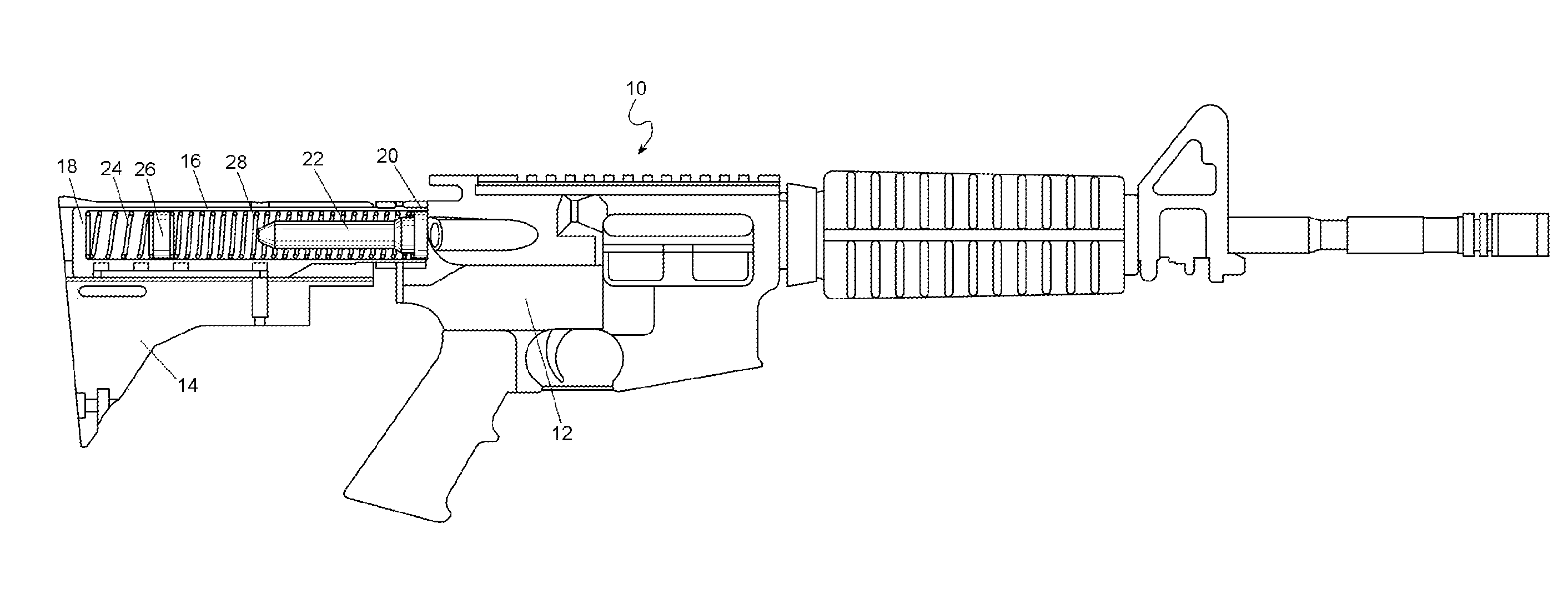
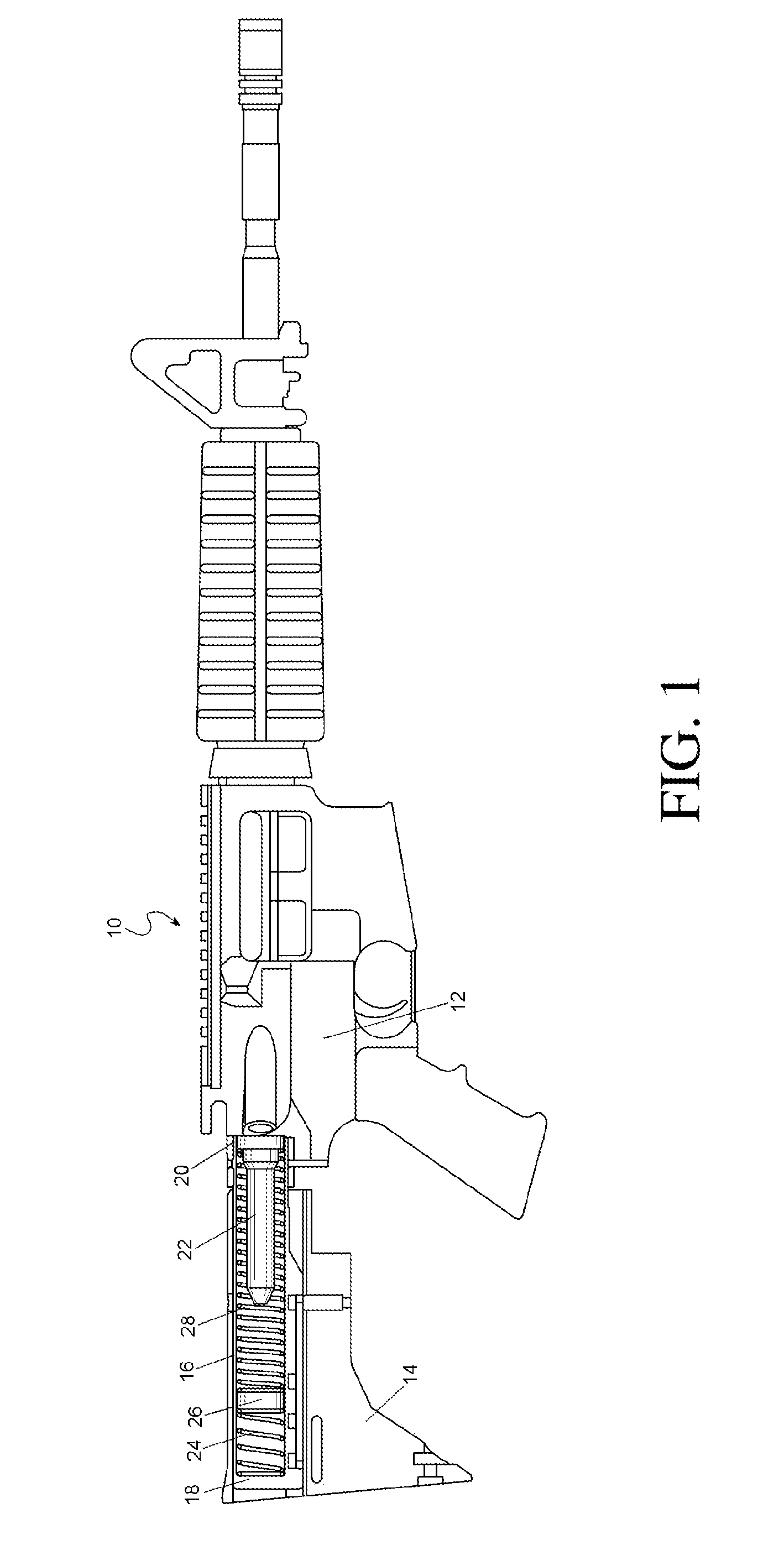
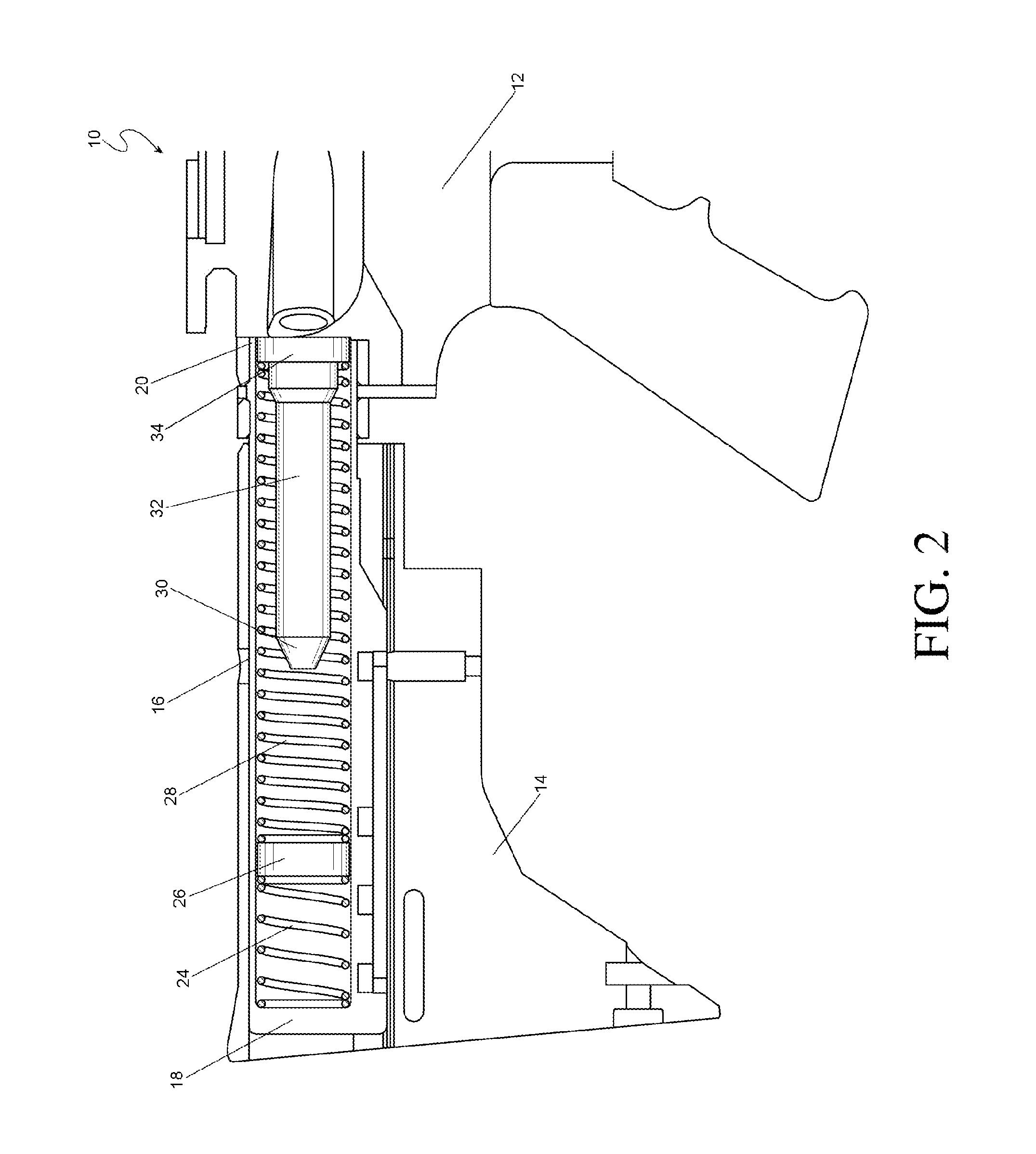
[0013]FIG. 1 illustrates a firearm 10 in the M16 family, such as an AR-15, shown from the side comprising a receiver 12 with a buttstock 14 attached to the rear of the receiver 12. The buttstock 14 contains a buffer tube 16 having a closed end 18 and an open end 20 which is shown cut away in FIGS. 1 and 2. The buffer tube 16 is attached to the receiver 12 at its open end 20. Contained within the buffer tube 16 is a buffer 22 along with the preferred embodiment of the recoil reducing spring system comprising: a short spring 24, a spacer 26, and a long spring 28. The buffer 22 comprises a small bumper end 30, a buffer body 32, and a larger stepped end 34 that is positioned within the long spring 28 at the opposite end from the spacer 26. FIG. 3 illustrates the components contained within the buffer tube including: the short spring 24, the spacer 26, the long spring 28, and the buffer 22.

[0014]The short spring 24, spacer 26, and long spring 28, which comprises the recoil reducing sprin...


PUM


Abstract

A firearm comprising a receiver with a bolt carrier assembly, a buttstock having a tube shaped opening adjacent to the rear of the bolt carrier assembly, a plurality of springs having similar inside and outside diameters disposed end-to-end within the tube shaped opening, and a buffer having a small diameter body disposed inside the inner diameter of the springs and having a large diameter head disposed where the foremost spring presses against the rear of the head and the front of the head presses against the rear of the bolt carrier assembly.

Description

CROSS REFERENCE TO RELATED APPLICATIONS[0001]This application claims priority to U.S. Provisional Application No. 61 / 752,387 filed on Jan. 14, 2013 which is incorporated herein by reference in its entirety.FIELD OF THE INVENTION[0002]The present invention relates in general to firearms and more particularly to recoil reducing mechanisms within firearms.BACKGROUND OF THE INVENTION[0003]A challenging problem that has plagued firearms from their inception is how to control recoil forces generated by the chemical reaction which propels projectiles. Firearm recoil can lead to discomfort and injury to the shooter who must maintain control of the firearm. Recoil also causes undesirable muzzle lift when a firearm is prevented from naturally moving backward. This muzzle lift prevents accurate firing unless the shooter waits long enough to restablilize the firearm thereby slowing the shooter's rate of fire. Minimizing the negative effects from recoil has been complicated by modern firearms wh...

Claims


Application Information

Patent Timeline
Patent Type & Authority Applications(United States)
IPC IPC(8): F41A25/12
CPCF41A25/12F41C23/06
Inventor HILSABECK, DANIEL
Owner HILSABECK DANIEL
Why Eureka
Try Eureka