Determining an Irradiation Plan for a Particle Irradiation Unit

a particle irradiation and plan technology, applied in radiation therapy, x-ray/gamma-ray/particle irradiation therapy, therapy, etc., to achieve the effect of reducing the number of isoenergy layers to be irradiated, reducing the overall irradiation duration, and facilitating patient comfor

Active Publication Date: 2015-07-16
SIEMENS HEALTHCARE GMBH
View PDF4 Cites 8 Cited by
  • Summary
  • Abstract
  • Description
  • Claims
  • Application Information

AI Technical Summary

Benefits of technology

[0018]If the number of raster points for an isoenergy layer is very small, the plan quality of the irradiation plan is not significantly improved by irradiating this isoenergy layer. As a result of this condition, the irradiation of such an isoenergy layer is avoided, as a result of which the irradiation time of a patient may advantageously be reduced.
[0040]The more the dose distribution determined for the irradiation plan produced corresponds to the predetermined dose distribution, the better the evaluation of the irradiation plan produced may be.
[0055]As a result of prescribing and observing the boundary condition, the number of isoenergy layers to be irradiated may be reduced compared to the prior art. As a result, the overall irradiation duration may be significantly shortened, which leads to greater comfort for the patient and to an increase in the effectiveness of the particle irradiation unit. The introduction advantageously requires no intervention in the beam application or in the accelerator itself, since this relates to a programming embodiment. As a result of a selectability of the conditions and a display of the effects on the quality of the irradiation plan, it is moreover advantageously possible to find an ideal compromise on a case-by-case basis between a reduced overall irradiation duration and the quality of the irradiation plan.

Problems solved by technology

The present embodiments are posed with the problem of keeping the overall irradiation duration as short as possible, while maintaining an acceptable plan quality when determining an irradiation plan for a particle irradiation unit.

Method used


Image

  • Determining an Irradiation Plan for a Particle Irradiation Unit
  • Determining an Irradiation Plan for a Particle Irradiation Unit
  • Determining an Irradiation Plan for a Particle Irradiation Unit

Examples


Embodiment Construction

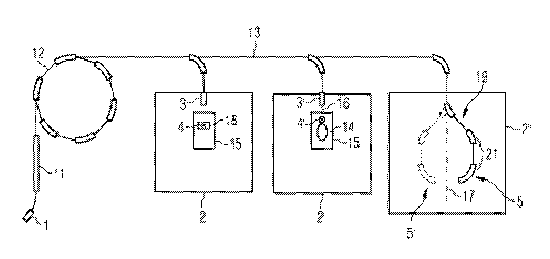
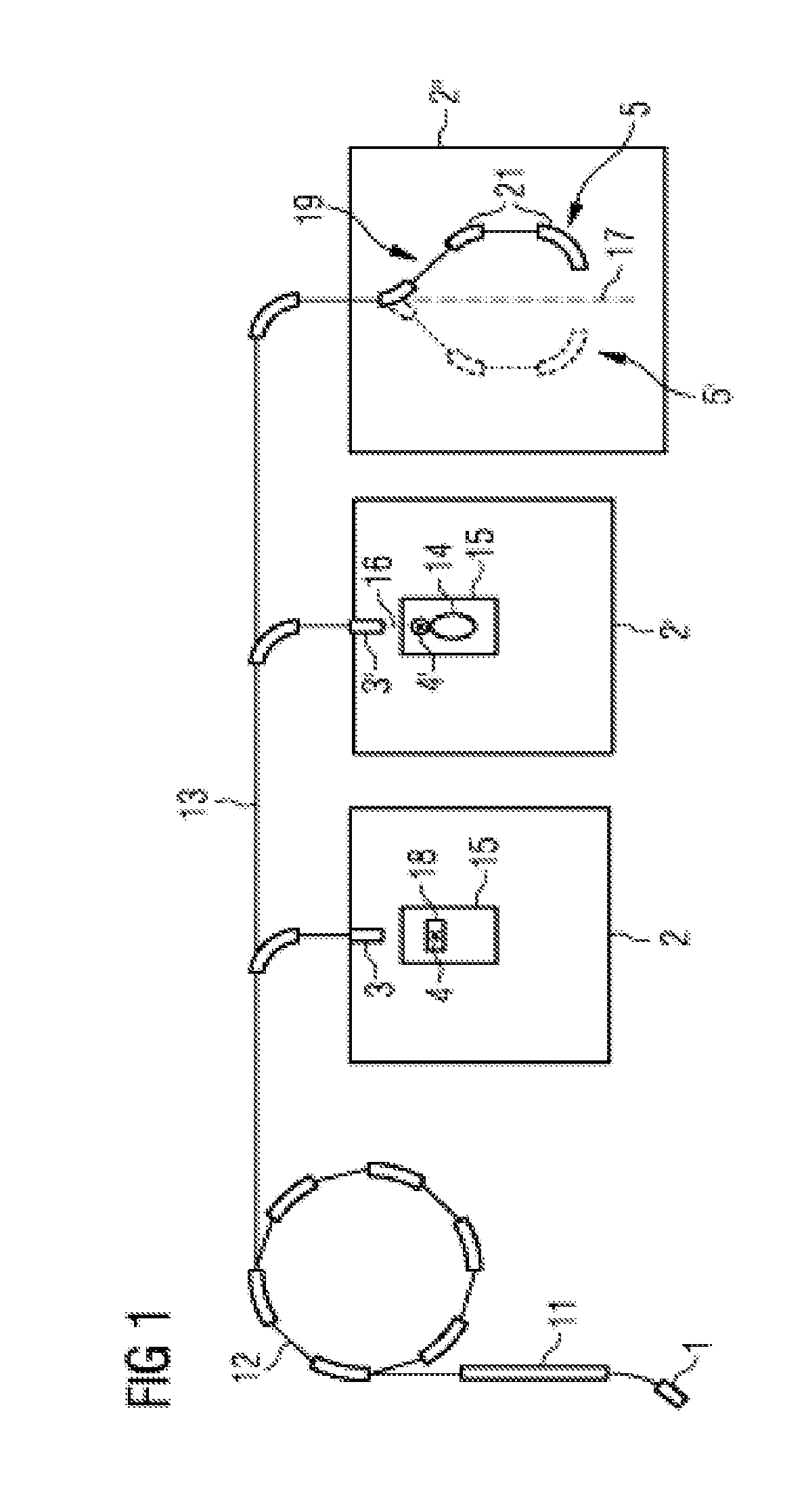
[0060]The particle irradiation unit 20 depicted schematically in FIG. 1 irradiates a patient 14 (see irradiation room 2′) lying on a positioning device 15 (e.g., a table) with a beam including particles 16, which is referred to as a particle beam 16 below. By way of example, such a particle beam 16 may be used to irradiate a tumor in the patient 14 using high-energy particles. However, it is also possible to use the particle irradiation unit 20 to irradiate an inanimate object 18, as is depicted in irradiation room 2 using the example of a water phantom 18.

[0061]By way of example, protons, pions, helium ions, carbon ions, but also ions from other elements are used as particles. To this end, the corresponding particles are generated in a particle source or ion source 1 and accelerated to a first energy level in a pre-accelerator 11 (e.g., a linear accelerator). The particles are subsequently accelerated to an energy required for the irradiation in a ring accelerator 12 (e.g., a synch...


PUM


Abstract

A target volume within a test object is irradiated according to an irradiation plan with a particle beam using a particle irradiation unit. The irradiation plan is determined in order to apply the energy of the particle beam in the target volume according to a predetermined dose distribution. In addition, a boundary condition is specified for at least one of the isoenergy layers and the irradiation plan is additionally specified such that the boundary condition is met for the at least one isoenergy layer. The boundary condition includes one or more of a minimum boundary energy, a maximum boundary energy, a minimum grid point number, a minimum total particle number, a minimum total dose, a minimum dose contribution to a total dose to be administered, a minimum contribution to a target function which is calculated for determining the irradiation plan, and a minimum dose compensation error.

Description

CROSS-REFERENCE TO RELATED APPLICATIONS[0001]The present patent document is a §371 nationalization of PCT Application Serial Number PCT / EP2013 / 061834, filed Jun. 7, 2013, designating the United States, which is hereby incorporated by reference, and this patent document also claims the benefit of DE 10 2012 212 341.5, filed on Jul. 13, 2012, which is also hereby incorporated by reference.TECHNICAL FIELD[0002]The present embodiments relate to a method and a device for determining an irradiation plan for a particle irradiation unit and an accordingly embodied particle irradiation unit.BACKGROUND[0003]By way of example, within the scope of therapy planning in particle radiotherapy, an irradiation plan that defines control parameters for irradiating an examination object is created in advance. The irradiation plan is used to plan the irradiation of an object in accordance with specific prescriptions (e.g., target volume or dose distribution).[0004]Particle radiotherapy is a well-establis...

Claims


Application Information

Patent Timeline
Patent Type & Authority Applications(United States)
IPC IPC(8): A61N5/10
CPCA61N5/1067A61N5/1031A61N2005/1087
Inventor BOHSUNG, JORGELSASSER, THILOGROZINGER, SVEN OLIVERKAWRAKOW, IWANKIM, JOHANNNEUHAUSER, ROBERTRIETZEL, EIKETHILMANN, OLIVER
Owner SIEMENS HEALTHCARE GMBH
Why Eureka
Try Eureka