Head-up display device

a display device and head-up technology, applied in the direction of lenses, instruments, transportation and packaging, etc., can solve the problems of unfavorable uniform virtual image and inability to configure the micro lens array, and achieve the effect of simple screen member configuration and reduction of uneven virtual imag

Active Publication Date: 2015-07-16
DENSO CORP
View PDF2 Cites 16 Cited by
  • Summary
  • Abstract
  • Description
  • Claims
  • Application Information

AI Technical Summary

Benefits of technology

[0007]The present disclosure has been made in consideration of the foregoing. It is an object of the disclosure to provide a head-up display device capable of maintaining a simple configuration of a screen member such as a micro lens array and reducing an uneven virtual image caused by laser beam interference.
[0009]According to the above-mentioned head-up display device, the direction to irradiate the first laser beam from the first generation portion differs from the direction to irradiate the second laser beam from the second generation portion. Therefore, a position to intensify the first laser beam diffracted by the curved surface portion due to interference may deviate from a position to intensify the second laser beam diffracted by the curved surface portion due to interference. When the first and second laser beams are overlapped each other, uneven brightness caused by one laser beam due to interference complements uneven brightness caused by the other laser beam due to interference to uniform the intensity distribution of laser beams reaching the visual region. Overlapping multiple laser beams irradiated from different irradiation directions can reduce an uneven virtual image caused by laser beam interference while maintaining a simple configuration of the screen member.

Problems solved by technology

This causes unevenness in an intensity distribution of the laser beam reaching a visual region and consequently unevenness in a virtual image for a display image viewed by a viewer.
The configuration of the micro lens array is inevitably complicated.

Method used


Image

  • Head-up display device
  • Head-up display device
  • Head-up display device

Examples


first embodiment

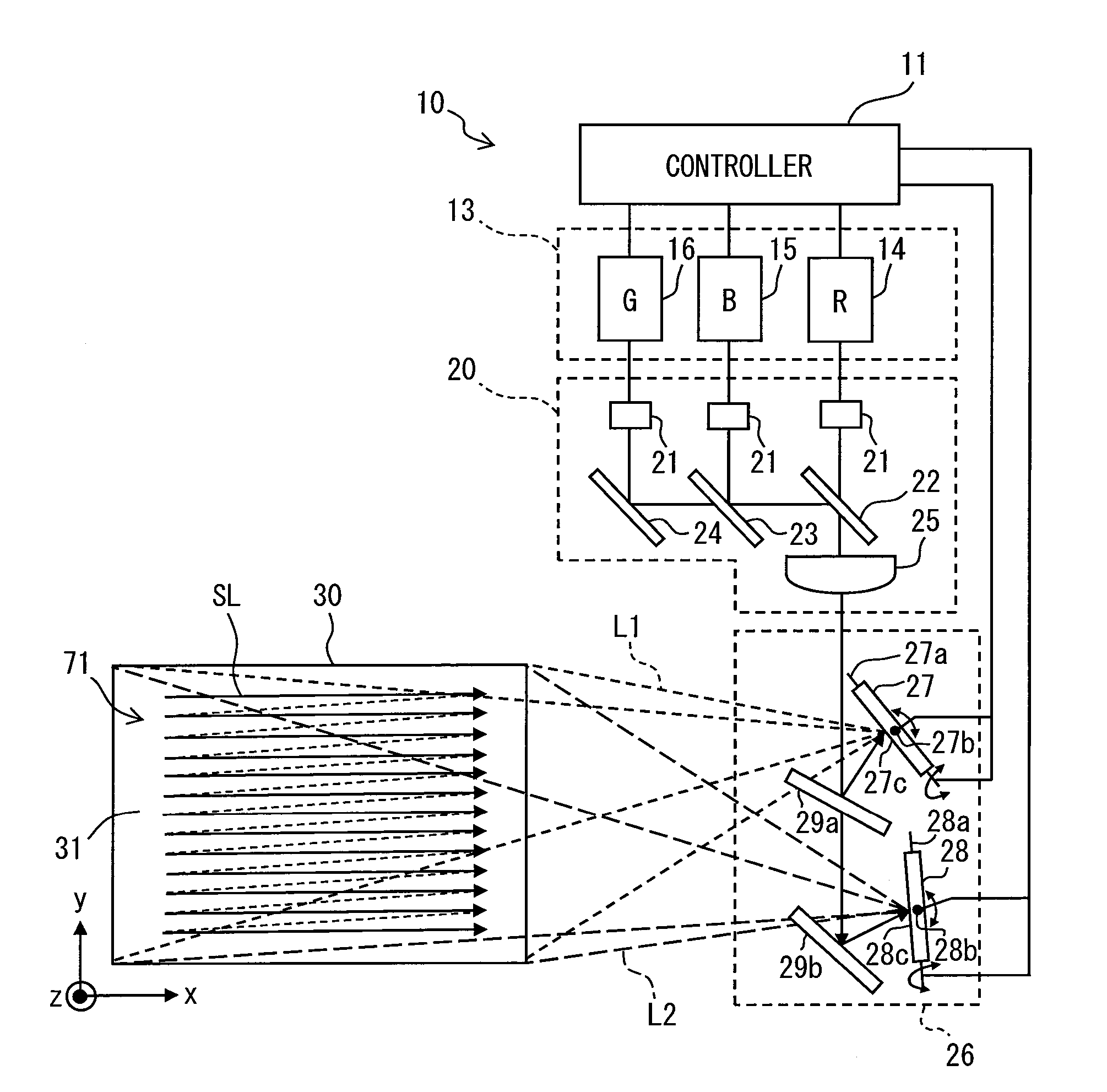
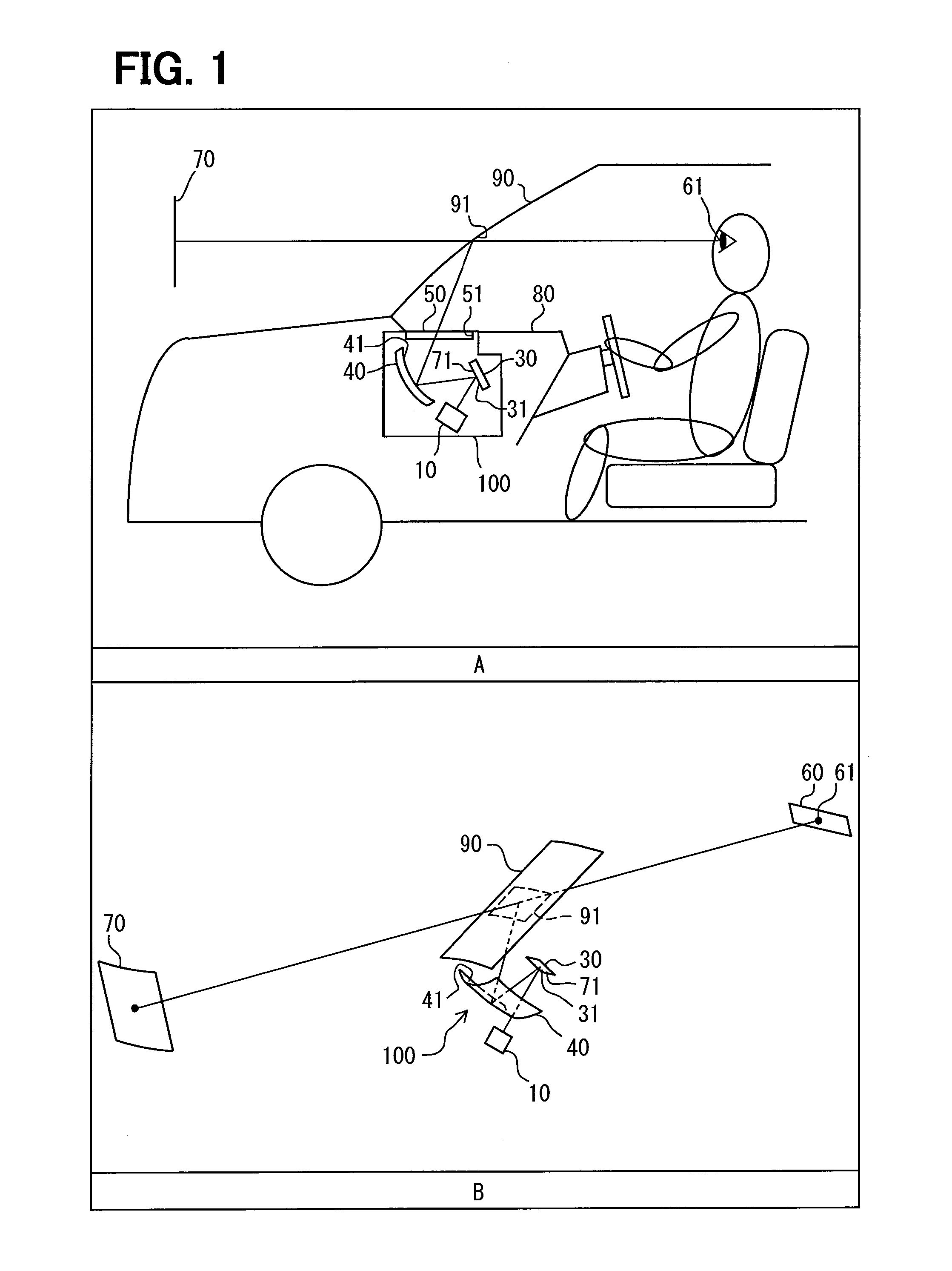
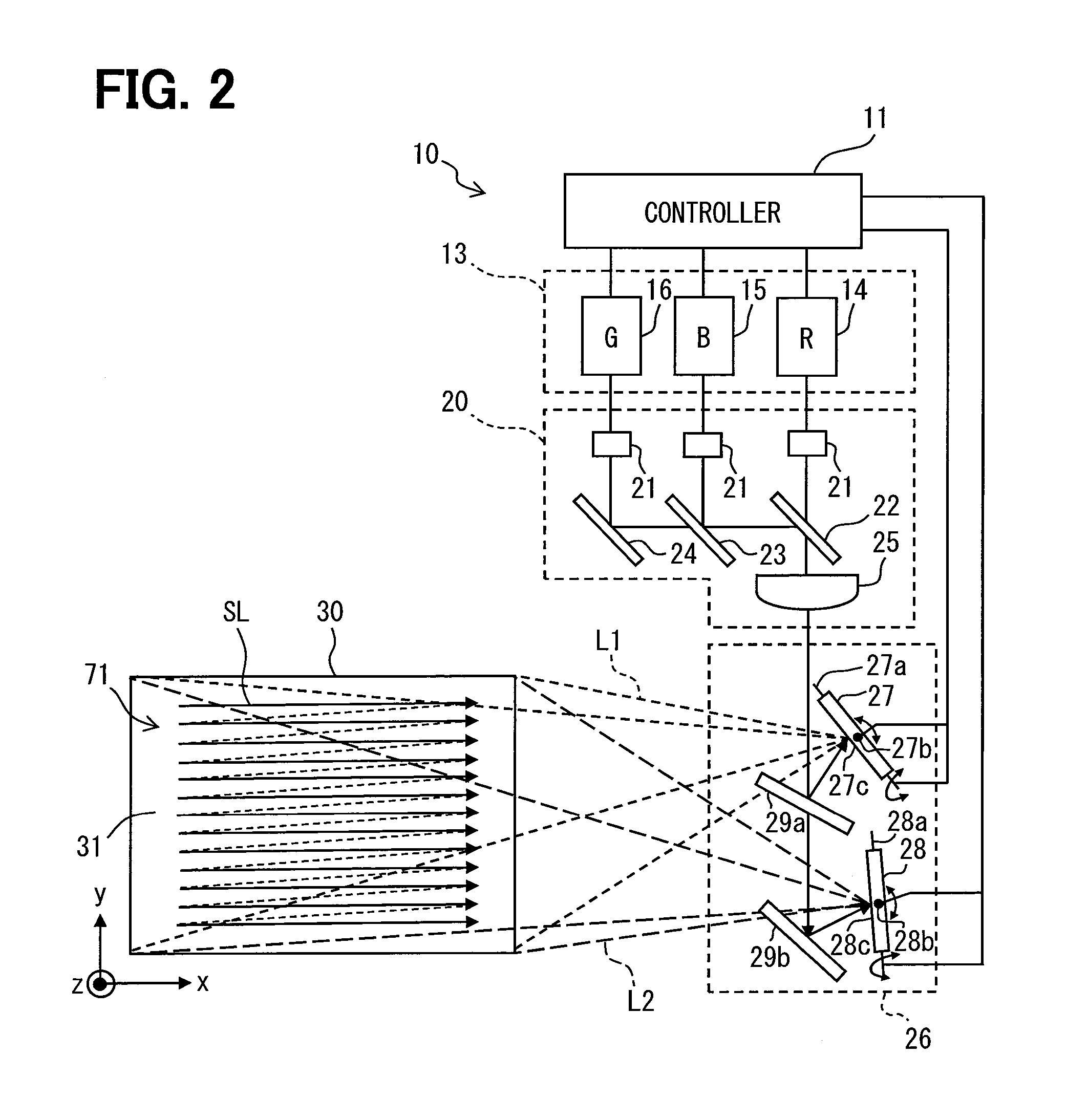
[0029]Parts A and B in FIG. 1 illustrate a head-up display device 100 according to the first embodiment. The head-up display device 100 is contained in an instrument panel 80 of a vehicle, for example. A display image 71 penetrates a translucent dust prevention cover 50 that covers an aperture 51. The head-up display device 100 projects the display image 71 onto a display member such as a windshield 90 of the vehicle and allows a virtual image 70 of the display image 71 to be visible from a predetermined eye box 60. The eye box 60 is sized 100 through 200 millimeters horizontally and 40 through 90 millimeters vertically, for example. A projection plane 91 is formed on the surface of the windshield 90 on a vehicle compartment side. The head-up display device 100 projects the display image 71 onto the projection plane 91. The light of the display image 71 is projected onto the concavely curved projection plane 91 that then reflects the light to the eye box 60. The light reaches a view...

second embodiment

[0055]The second embodiment illustrated in FIGS. 8 and 9 is a modification of the first embodiment. As illustrated in FIG. 8, a MEMS mirror portion 226 according to the second embodiment includes half mirrors 29a and 229a, the mirror reflector 29b, the first scanner 27, the second scanner 28, and a third scanner 227. The half mirror 29a reflects approximately one third of a laser beam irradiated from the optical portion 20 to the first scanner 27 and transmits the remainder, i.e., approximately two thirds of the laser beam to the half mirror 229a. The half mirror 229a is configured to be substantially equal to the half mirror 29a and is placed so that the reflection surface faces the mirror 29a and the third scanner 227. The half mirror 229a reflects approximately half the laser beam penetrating the half mirror 29a to the third scanner 227 and transmits the remainder, i.e., approximately half the laser beam to the mirror reflector 29b. The half mirror 29a and 229a and the mirror ref...

third embodiment

[0062]The third embodiment illustrated in FIGS. 10 through 14 is another modification of the first embodiment. In a laser scanner 310 illustrated in FIG. 10, a MEMS mirror portion 326 includes a horizontal scanner 327 and a vertical scanner 328 connected to the controller 11. The horizontal scanner 327 and the vertical scanner 328 are provided with rotation axes 327a and 328a and MEMS reflection surfaces 327b and 328b, respectively. The MEMS reflection surfaces 327b and 328b each contain a metal thin film formed by depositing aluminum.

[0063]The horizontal scanner 327 is placed so that the reflection surface 327b faces the optical portion 20 and the vertical scanner 328. Based on a drive signal from the controller 11, the horizontal scanner 327 rotationally displaces the MEMS reflection surface 327b around the rotation axis 327a. The vertical scanner 328 is placed so that the MEMS reflection surface 328b faces the MEMS reflection surface 327b of the horizontal scanner 327 and a scree...


PUM


Abstract

A head-up display device including a screen member, a first generation portion, and a second generation portion is provided. The screen member is provided with multiple optical elements each of which has a curved surface portion and forms a scan surface by an array of the curved surface portions. The first generation portion generates a first laser beam that is irradiated to the scan surface to draw a display image. The second generation portion generates a second laser beam to draw a display image that is irradiated to the scan surface from a direction different from the first laser beam.

Description

CROSS-REFERENCE TO RELATED APPLICATIONS[0001]The present application is based on Japanese Patent Application No. 2012-128235 filed on Jun. 5, 2012, the content of which is incorporated herein by reference.TECHNICAL FIELD[0002]The present disclosure relates to a head-up display device that projects a display image generated by scanning a laser beam and thereby makes a virtual image of the display image visible.BACKGROUND ART[0003]It is conventionally known that a head-up display device projects a display image onto a vehicle windshield and thereby makes a virtual image of the display image visible from a predetermined visual region. As one type of such a device, for example, Patent Literature 1 discloses a scanning beam head-up display device including a micro lens array having many small lenses and a beam generator to generate a laser beam that is irradiated to the micro lens array and draws a display image.PRIOR ART LITERATURESPatent Literature[0004]Patent Literature 1: Japanese Tr...

Claims


Application Information

Patent Timeline
Patent Type & Authority Applications(United States)
IPC IPC(8): G02B26/10G02B27/01
CPCG02B26/101G02B27/0101G02B2027/0159G02B2027/0114G02B2027/0154G02B27/0149G02B27/0905G02B27/48B60K35/00G02B26/0883B60K2370/1529B60K2370/334B60K37/00G02B3/00G02B5/04G02B26/10G02B27/01Y02T10/84
Inventor ANDO, HIROSHIFUJIKAWA, TAKAYUKI
Owner DENSO CORP
Why Eureka
Try Eureka