
Wireless communication device and communication terminal

a communication terminal and wireless communication technology, applied in the field of wireless communication devices and communication terminals, can solve the problems of affecting communication quality, increasing accuracy in error detection, and sound quality distorted, and achieve the effect of wideband sound quality

Active Publication Date: 2015-07-16
PANASONIC INTELLECTUAL PROPERTY MANAGEMENT CO LTD
View PDF2 Cites 4 Cited by
  • Summary
  • Abstract
  • Description
  • Claims
  • Application Information

AI Technical Summary

Benefits of technology

The present invention provides a wireless communication device and a communication terminal that can maintain sound quality without changing a sound data rate through use of a fixed-size packet even when the communication environments become worse. This is achieved by individually processing high frequency and low frequency data using an error detection code that is transmitted after replacement of some bits of the low range data. This ensures that even when the communication environments become worse, wideband sound quality can be maintained by a fixed-size packet without changing a data rate of sound.

Problems solved by technology

When a user carries a wireless voice communication system in one's hand, such as a cellular phone and a cordless phone, or uses the system at a location where ambient circumstances change, variations occur in received signal strength indicator, a distance between devices, and an interference radio wave, which greatly affects communication quality.
As a result, when a communication environment becomes worse, sound quality is somewhat distorted, but accuracy in error detection is increased.
For this reason, sound quality is considered to become deteriorated.
However, if the sound quality changes for the worse in sequence as the communication environment becomes worse, the user will experience inconvenience in using the wireless telephone system.

Method used


Image

  • Wireless communication device and communication terminal
  • Wireless communication device and communication terminal
  • Wireless communication device and communication terminal

Examples


embodiment

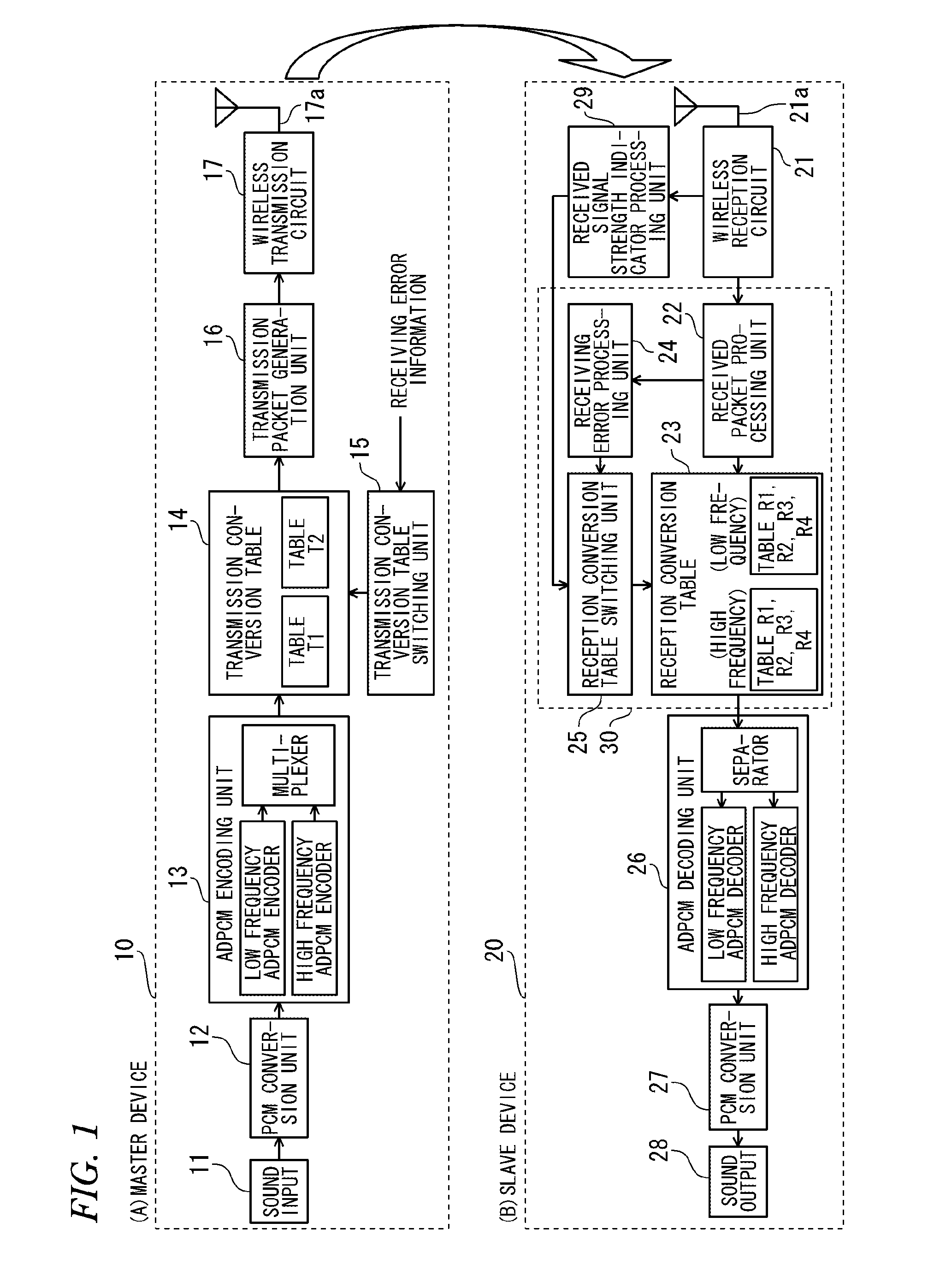
[0037]By reference to the drawings, a wireless communication device according to an embodiment of the present invention is described by taking a cordless telephone as an example. FIG. 1 is a block diagram showing a cordless telephone according to an embodiment of the present invention. In FIG. 1, (A) is a block diagram showing a transmission function of a master device (a first communication terminal), and (B) is a block diagram showing a receiving function of a slave device (a second communication terminal). For the sake of convenience, FIG. 1 illustrates only the transmission function of the master device and the receiving function of the slave device. However, each of the master device and the slave device has both functions.

[0038]The cordless telephone includes the master device 10 and one or more slave devices 20, as shown in FIG. 1. The cordless telephone is a wireless communication device that establishes a digital link on a wireless channel between the master device 10 and t...


PUM


Abstract

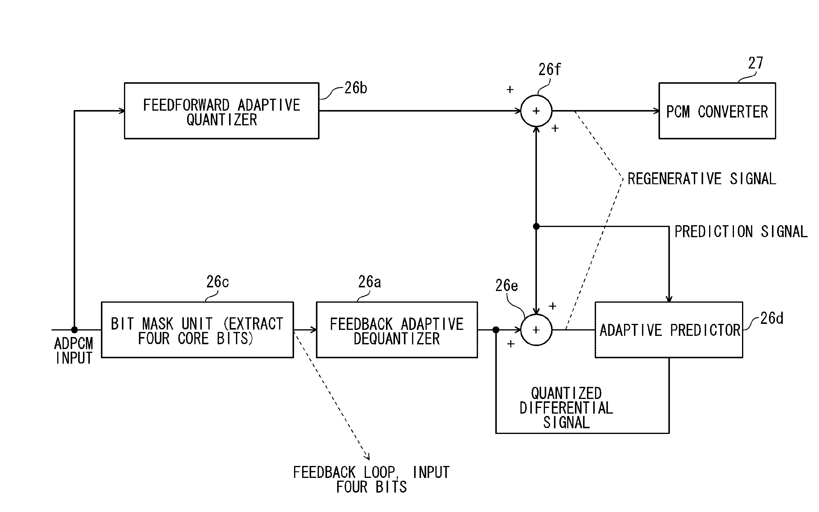
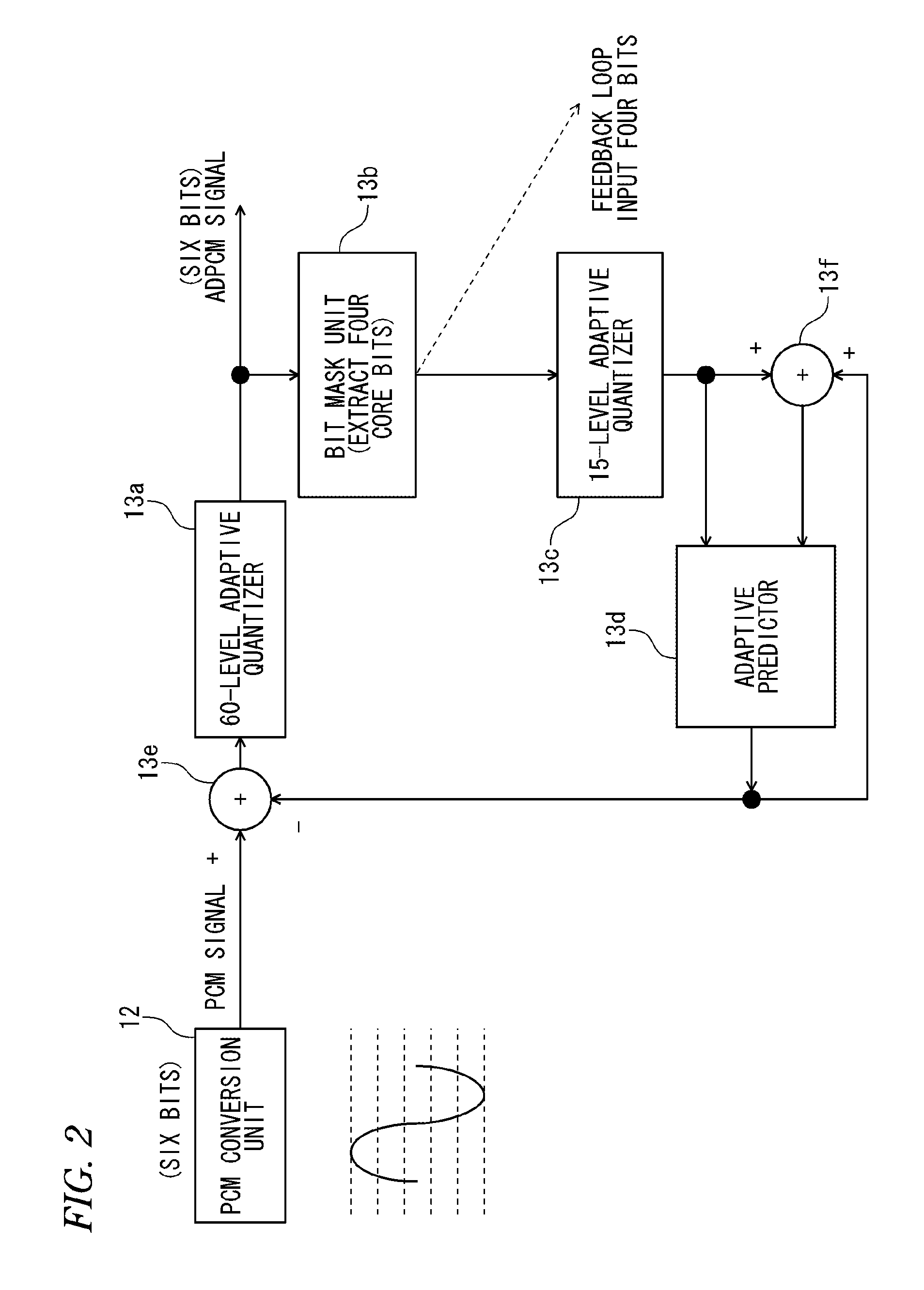
A device divides a sampled sound signal into a high frequency signal and a low frequency signal, individually encodes the high frequency signal and the low frequency signal, and generates error detection code pertinent to the high frequency ADPCM data and the low frequency ADPCM data. The device replaces data pertinent to some of a plurality of bits which configure the low frequency ADPCM data with the error detection code and transmits them. A receiver side receives the high frequency ADPCM data and the low frequency ADPCM data, and individually processes the high frequency ADPCM data and the low frequency ADPCM data in accordance with a value of the error detection code.

Description

BACKGROUND[0001]1. Field of the Invention[0002]The present invention relates to a wireless communication device and a communication terminal that perform a communication by use of sound packets.[0003]2. Description of the Related Art[0004]When a user carries a wireless voice communication system in one's hand, such as a cellular phone and a cordless phone, or uses the system at a location where ambient circumstances change, variations occur in received signal strength indicator, a distance between devices, and an interference radio wave, which greatly affects communication quality. A known countermeasure against the problems is; for instance, a technique described in relation to a wireless telephone system as disclosed in JP-T-2002-509387.[0005]The wireless telephone system of JP-T-2002-509387 is made up of a base unit that has a base transceiver and at least one wireless handset and that is connectable with one external phone line. The wireless handset and the base unit implement c...

Claims


Application Information

Patent Timeline
Patent Type & Authority Applications(United States)
IPC IPC(8): H04L1/00H03M3/04
CPCH04L1/0061H03M3/042H04L1/0042G10L19/005G10L19/0204H03M7/3046H03M13/09H04B14/068H04L1/0041
Inventor SHIBUTA, AKIRASUWA, YUTAKAISHIHARA, HIROYUKIOBANA, KYOICHI
Owner PANASONIC INTELLECTUAL PROPERTY MANAGEMENT CO LTD
Learn More