Centrifugal impeller for a blower

Active Publication Date: 2015-07-23
JOHNSON ELECTRIC INTERNATIONAL AG
View PDF5 Cites 0 Cited by
  • Summary
  • Abstract
  • Description
  • Claims
  • Application Information

AI Technical Summary

Benefits of technology

[0019]In embodiments of the present invention, the blade mounting holes of the cover plate close to the air inlet are configured to have a circular shape or a regular polygon shape, which reduces or even eliminates stress concentration at the blade mounti

Problems solved by technology

One drawback of the conventional blower is that, when the motor speed is high, especially higher than 33000 RPM, it is known for

Method used


Image

  • Centrifugal impeller for a blower
  • Centrifugal impeller for a blower
  • Centrifugal impeller for a blower

Examples


Example

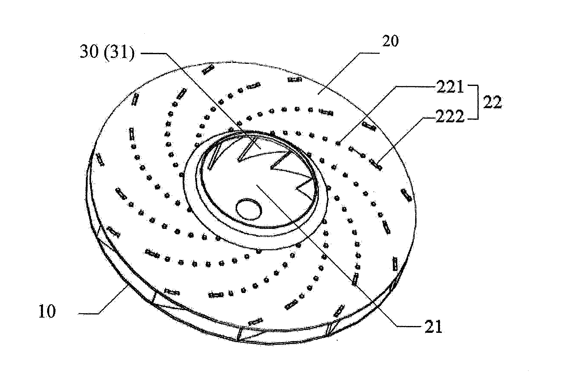
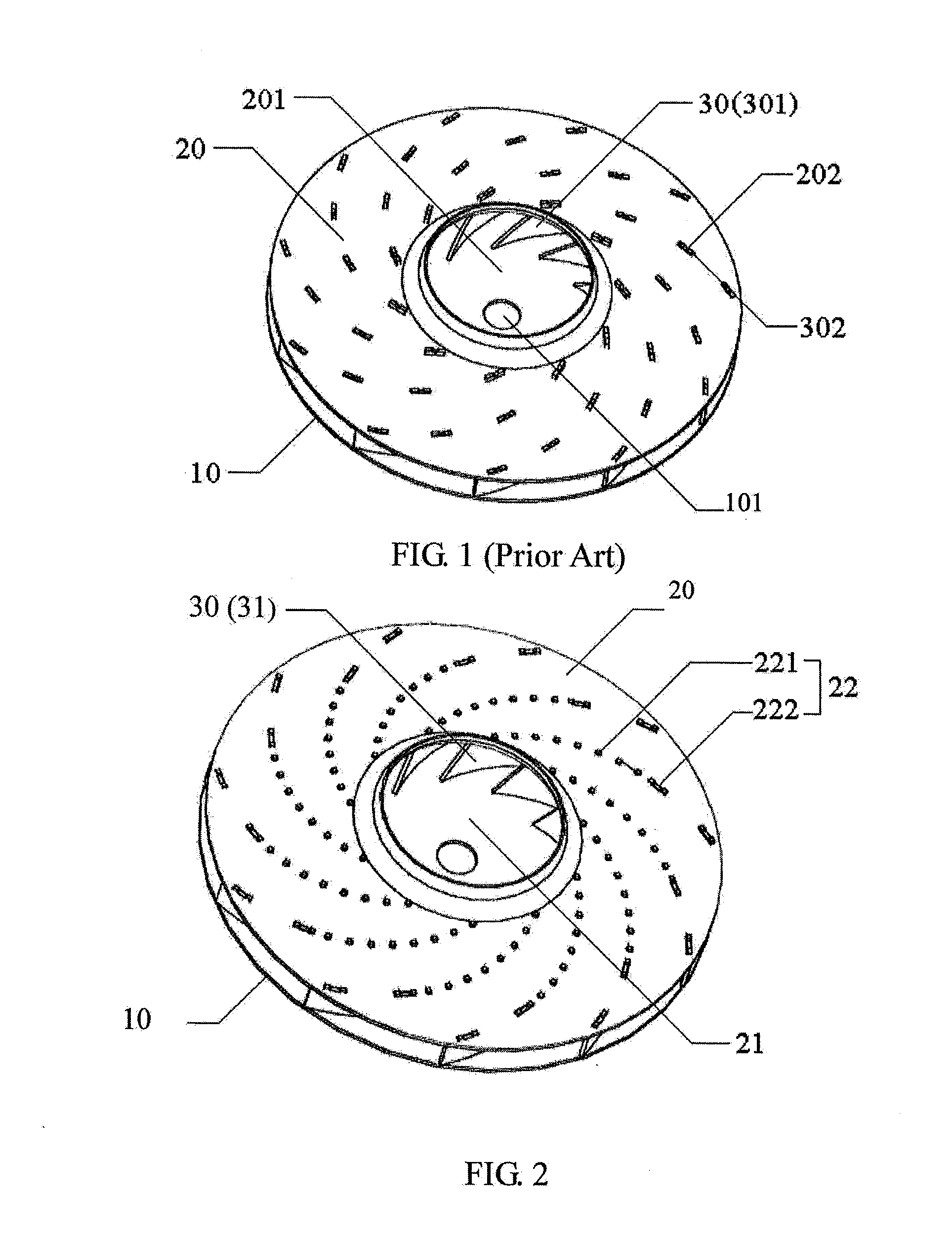
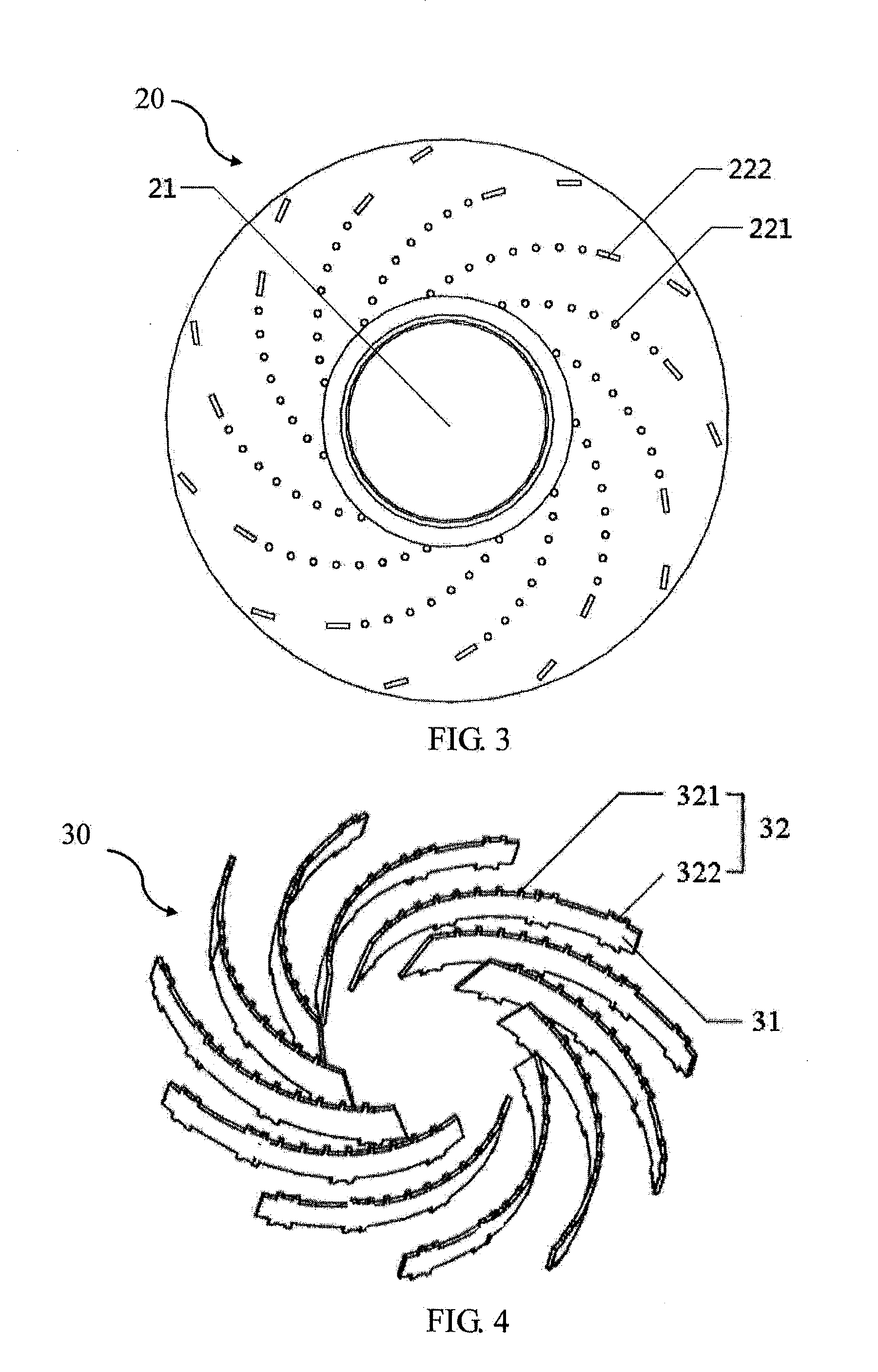
[0031]A centrifugal impeller in accordance with one embodiment of the present invention is described below with reference to FIGS. 2 to 7. The centrifugal impeller has a base plate 10, a cover plate 20, and a blade assembly 30 arranged between the base plate 10 and the cover plate 20. The cover plate 20 forms an air inlet 21 at a central position of the cover plate 20.

[0032]Preferably, the base plate 10, the cover plate 20 and the blade assembly 30 are all fabricated from a metal material, ideally an aluminum material.

[0033]The blade assembly 30 includes a plurality of curved blades 31 arranged annularly around the air inlet 21. The base plate 10 includes a plurality of blade mounting portions. Each blade mounting portion extends outwardly along a helical line for mounting one corresponding blade 31. Similarly, the cover plate 20 also includes a plurality of blade mounting portions. Each blade mounting portion of the cover plate 20 extends outwardly along a helical line for mounting...


PUM


Abstract

A centrifugal impeller for a blower has a base plate, a cover plate, and a plurality of curved blades mounted between the base plate and the cover plate. The base plate and the cover plate have blade mounting portions including a plurality of mounting holes. Cover plate mounting portions and base plate mounting portions project from each blade and engage with the mounting holes of the cover plate and base plate, respectively. The mounting holes of the cover plate include first mounting holes arranged outwardly from a central region. The first mounting holes have a circular shape. The cover plate mounting portions of each blade include first mounting protrusions engaged with the first mounting holes.

Description

CROSS REFERENCE TO RELATED APPLICATIONS[0001]This non-provisional patent application claims priority under 35 U.S.C. § 119(a) from Patent Application No. 201410033397.4 filed in The People's Republic of China on Jan. 23, 2014, the entire contents of which are hereby incorporated by reference.FIELD OF THE INVENTION[0002]This invention relates to a blower and in particular, to a centrifugal impeller of the blower. It also relates to electrical appliances, such as a vacuum cleaner or a hand drier, that use the blower.BACKGROUND OF THE INVENTION[0003]As a main component of a hand drier, a blower comprises a centrifugal impeller and a motor for driving the impeller. The impeller moves air to form a pressurized airflow that is discharged via an air outlet. A hand drier and a vacuum cleaner typically employ a centrifugal blower with a central air inlet and a peripheral air outlet.[0004]Referring to FIG. 1, a conventional centrifugal impeller has a base plate 10, a cover plate 20, and a bla...

Claims


Application Information

Patent Timeline
IPC IPC(8): F04D29/28F04D17/08
CPCF04D17/08F04D29/281F04D29/626
Inventor SHEN, JUN FENGLEUNG, CHING HANGTAM, SIU CHUN
Owner JOHNSON ELECTRIC INTERNATIONAL AG
Why Eureka
Try Eureka