
Annular stack of laminations comprised of single-tooth stacks and method for manufacturing a stack of lamination

a technology of single-tooth stacks and laminations, which is applied in the direction of manufacturing stator/rotor bodies, magnetic circuit shapes/forms/construction, other domestic objects, etc., can solve the problems of short circuit, poor electrical properties of the stack of laminations as well as the geometric conditions, etc., and achieves a strong and easy-to-dissolve adhesive bond

Inactive Publication Date: 2015-07-23
KIENLESPIESS GMBH
View PDF7 Cites 6 Cited by
  • Summary
  • Abstract
  • Description
  • Claims
  • Application Information

AI Technical Summary

Benefits of technology

The patent is about a way to make sure that laminations of pole shoes are positioned accurately. This is done by creating projections and depressions on the surfaces of the pole shoes that fit together like a puzzle. The adhesive is applied in the form of drops, which allows for easy removal and re-attachment of the pole shoes. The technical effect of this design is more precise positioning and easier assembly of the laminations.

Problems solved by technology

In both the joining and separating process, undesirable deformations often arise in the area of the projections and depressions, which worsens the electrical properties of the stack of laminations as well as the geometric conditions.
The chips can lead to a short circuit when using the stack of laminations in electrical equipment.

Method used


Image

  • Annular stack of laminations comprised of single-tooth stacks and method for manufacturing a stack of lamination
  • Annular stack of laminations comprised of single-tooth stacks and method for manufacturing a stack of lamination
  • Annular stack of laminations comprised of single-tooth stacks and method for manufacturing a stack of lamination

Examples


Embodiment Construction

[0034]The laminations in the form of single teeth described below are used to form annular stack of laminations, which are used in electrical machines. For example, such stacks of laminations are used in the rotors and / or stators of electric motors.

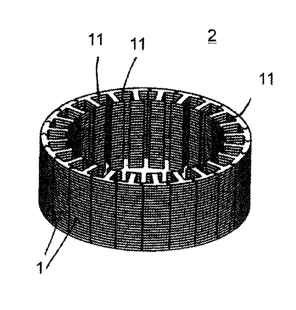
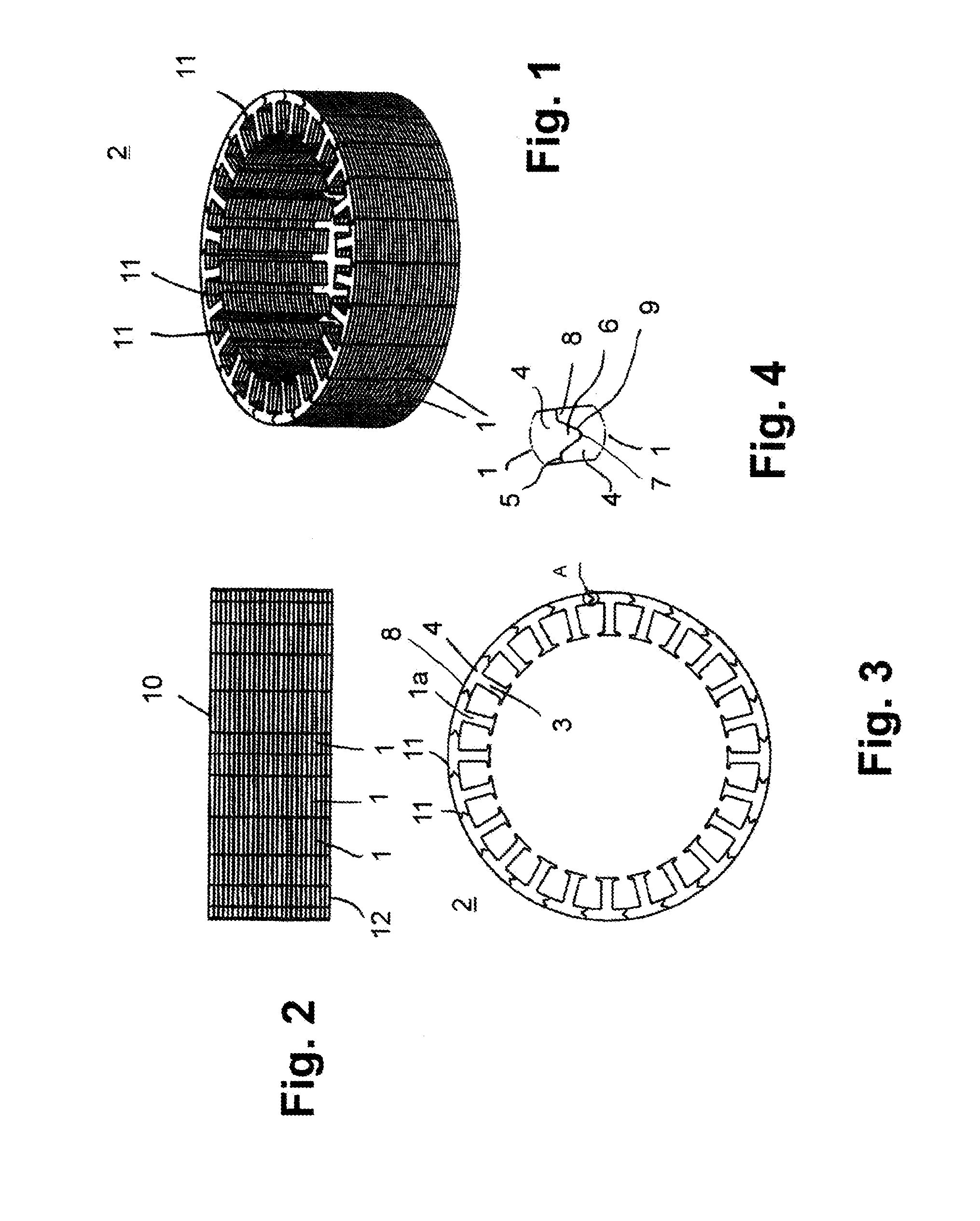
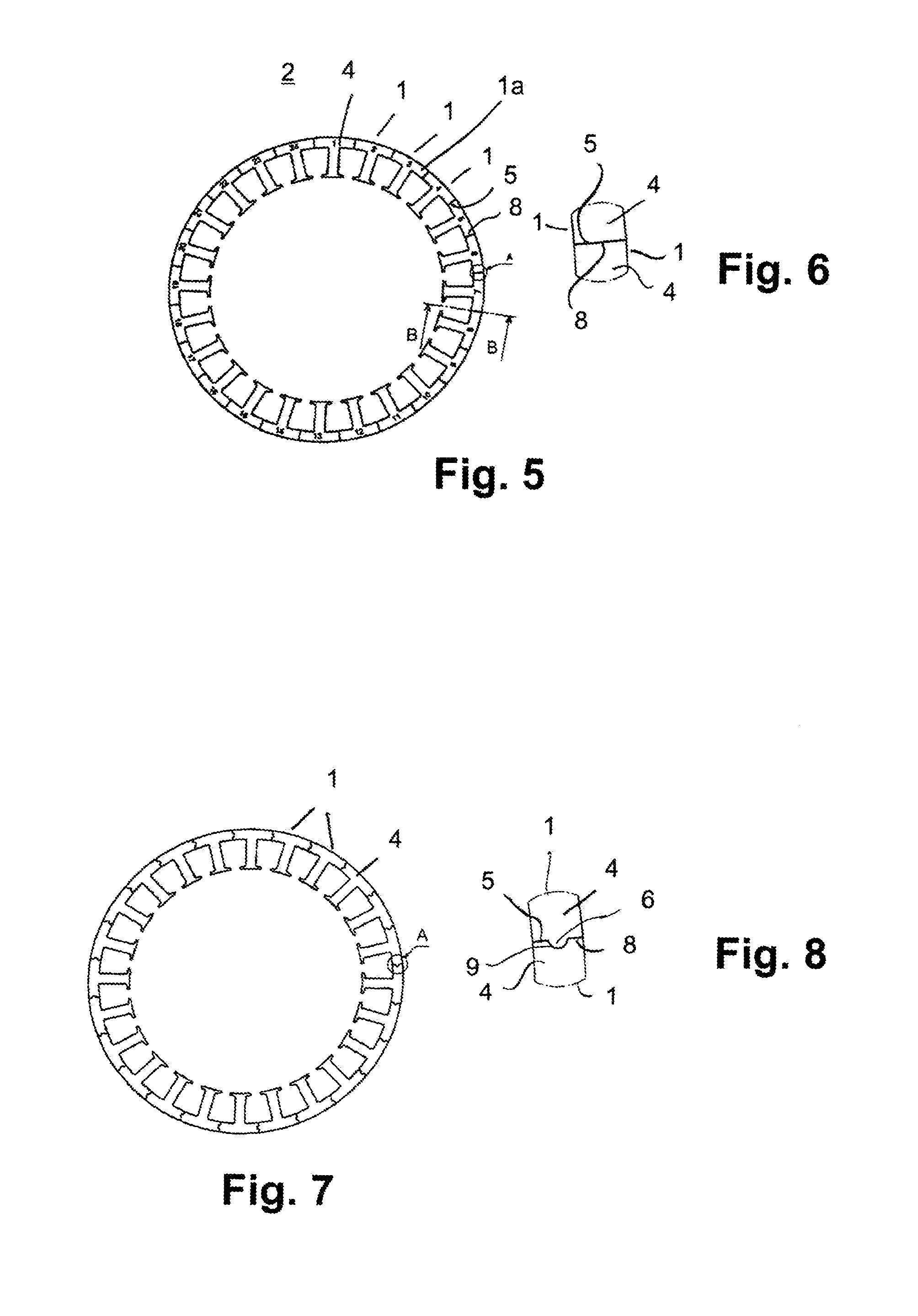
[0035]The laminations described below are single teeth which form a ring. The punched rings are subsequently assembled into an annular stack of laminations 2. It consists of abutting single-tooth stacks 1. As exemplarily indicated on FIG. 5, they are consecutively numbered. In the depicted exemplary embodiment according to FIG. 5, the annular stack of laminations 2 consists of 24 single-tooth stacks 1. The single-tooth stacks 1 are assembled into the annular stack of laminations 2 for transport to the customer. The customer divides the annular stack of laminations 2 into the single-tooth stacks 1, so as to coat and wind the latter. The single-tooth stacks 1 are then joined back together again in the previous sequence to yield the stack of...


PUM

PropertyMeasurementUnit
Forceaaaaaaaaaa
Adhesivityaaaaaaaaaa
Widthaaaaaaaaaa

Abstract

The annular stack of laminations provides adjoined single-tooth stacks, each exhibiting a pole body and a pole shoe. Adjacent single-tooth stacks abut against each other with the faces of their pole shoes. Adjacent single-tooth stacks are joined together by at least one adhesive bond in such a way that the adhesive bond can be dissolved by applying a force so as to detach the single-tooth stacks from the annular stack of laminations. While manufacturing the stack of laminations, an adhesive is at least partially introduced between the single-tooth stacks. The single-tooth stacks can be detached from the annular stack of laminations by the user for coating and winding purposes. The adhesive bond ensures that the single-tooth stacks are reliably held together during transport.

Description

BACKGROUND OF THE INVENTION[0001]The invention relates to an annular stack of lamination consisting of adjoined single-tooth stacks, which each exhibit at least one pole body and at least one pole shoe, wherein adjacent single-tooth stacks abut each other with the faces of their pole shoes. The invention further relates to a method for manufacturing such a stack of lamination, in particular of the aforementioned kind, in which single-tooth stacks are joined with the faces of the pole shoes adjoining each other.[0002]Known in the art is to put together single-tooth stacks composed of single-tooth laminations into an annular stack of laminations. In order to be able to put the single-tooth stacks together into an annular stack of laminations, the pole shoes of the single-tooth stacks exhibit defined contact surfaces, preferably a projection on their one face and a depression complementary thereto on their opposing face. The projection is shaped like a pitch circle, and extends over mo...

Claims


Application Information

Patent Timeline
IPC IPC(8): H02K1/06B32B37/12B32B38/00H02K15/02B32B37/18
CPCH02K1/06H02K15/02B32B37/18B32B2457/00B32B37/1292H02K2201/09B32B38/0004H02K1/08H02K15/022H02K1/148Y10T156/1062
Inventor BURKHARDT, GEORG
Owner KIENLESPIESS GMBH
Learn More