
Motion and control system

Inactive Publication Date: 2015-07-23
SCHNEIDER TOSHIBA INVERTER EUROPE SAS
View PDF12 Cites 2 Cited by
  • Summary
  • Abstract
  • Description
  • Claims
  • Application Information

AI Technical Summary

Benefits of technology

The invention provides a redundant motion and control system that reduces the cost and size of the system. This is achieved by including a standby power stage in the motion and control device. The controller will reset the main power stage and drive it for a short time, if a fault signal is received again. This ensures that the system operates efficiently and prevents downtime due to faults.

Problems solved by technology

However, there is a big problem in such a redundant system, and applying 2 motion and control devices in a cabinet will lead to a significant increase of the cost and size of the system.

Method used


Image

  • Motion and control system
  • Motion and control system
  • Motion and control system

Examples


Embodiment Construction

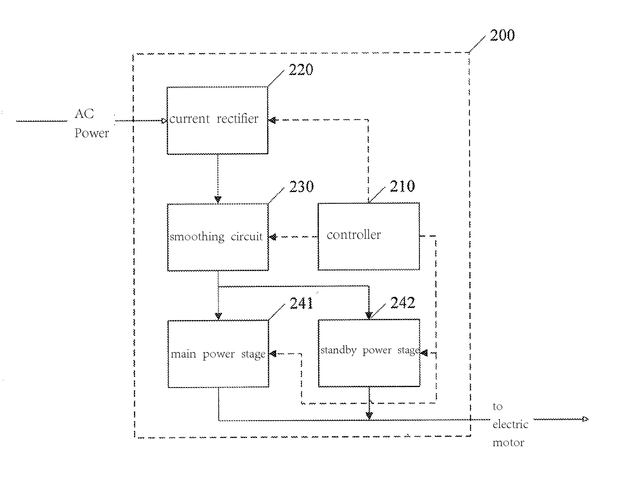
[0027]Considering that the failure probability of the inverter of a motion and control device is higher and the cost of the IGBT power stage thereof makes up only a small part, compared with the whole device, the redundant design of the inner power stage of a single motion and control device is used in the present invention to realize the redundant system of the motion and control device, instead of adding a standby motion and control device.

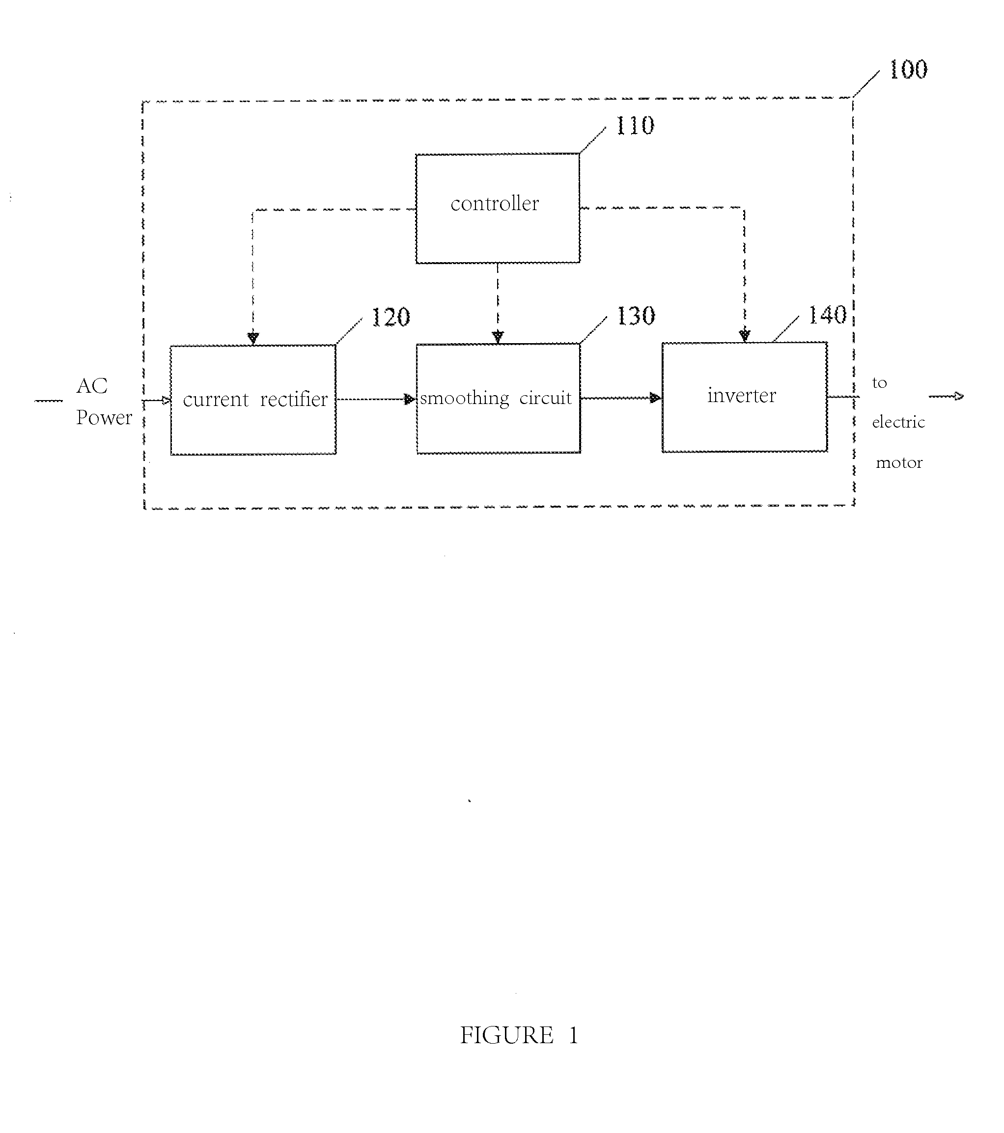
[0028]FIG. 3 is a block diagram of the motion and control system 200 of the embodiment according to the present invention. With reference to FIG. 3, the motion and control system 200 includes a controller 210, a current rectifier 220, a smoothing circuit 230, a main power stage 241, and a standby power stage 242. The difference between the redundant system of the motion and control system 200 and that of the traditional motion and control system (composed of 2 motion and control devices 100 of FIG. 1) is that, based on one motion and control dev...


PUM


Abstract

A motion and control system, comprising: a current rectifier (220) for transforming an alternating current into a direct current; a smoothing circuit (230) for performing smoothing processing on the wave form of the direct current output by the current rectifier (220); a main power stage (241) and a standby power stage (242) which are connected between the smoothing circuit (230) and an electric motor in parallel; and a controller (210) which, under a normal working mode, drives the main power stage (241) to transform a direct current voltage from the smoothing circuit (230) into an alternating current voltage provided for the electric motor, and when it is determined that a fault of the main power stage (241) has occurred, drives the standby power stage (242) to transform the direct current voltage from the smoothing circuit (230) into the alternating current voltage provided for the electric motor. By comprising a standby power stage (242) in a motion and control device, the cost and size of the system are reduced.

Description

FIELD OF INVENTION[0001]The present invention relates to the field of electric motor control. Specifically, it relates to the redundant system of a motion and control system.BACKGROUND ART[0002]A motion and control device (also known as “frequency converter”) is usually used for the control of the speed and position of the electric motor in industry, especially, in the environment of high precision machining and energy saving.[0003]FIG. 1 is a block diagram of a regular motion and control device 100. With reference to FIG. 1, a motion and control device 100 comprises a controller 110, a current rectifier 120, a smoothing circuit 130 and an inverter 140.[0004]The current rectifier 120 is used for transforming an input alternating current power source into a direct current power source. The smoothing circuit 130 is used for performing smoothing processing on the wave form of the direct current. The inverter 140 is used for transforming the smoothed direct current into an alternating c...

Claims


Application Information

Patent Timeline
IPC IPC(8): H02P6/12
CPCH02P6/12H02P29/032
Inventor LIAN, XIAOFAN
Owner SCHNEIDER TOSHIBA INVERTER EUROPE SAS
Features
  • Generate Ideas
  • Intellectual Property
  • Life Sciences
  • Materials
  • Tech Scout
  • Unparalleled Data Quality
  • Higher Quality Content
  • 60% Fewer Hallucinations
Learn More