Method and system for linearizing an amplifier using transistor-level dynamic feedback

Active Publication Date: 2015-07-23
DARWISH ALI MOHAMED
View PDF5 Cites 6 Cited by
  • Summary
  • Abstract
  • Description
  • Claims
  • Application Information

AI Technical Summary

Benefits of technology

[0027]FIG. 16A shows an example table of the control voltages required for given output power back offs to achieve a desired constant relative phase shift.

Problems solved by technology

For example, as the power level of an input signal increases above such a threshold, an amplifier's ability to provide gain will often increasingly degrade.
This can result in a distorted output signal from the amplifier due to the low-power elements of the input signal having been amplified with a higher gain factor than the high-power elements of the input signal.
However, this may be undesirable as such a restriction limits the power efficiency that can be obtained when using such an amplifier.
The problem with this approach is that it often creates unwanted intermodulation distortion byproducts that arise from small but significant mismatches between the pre-di

Method used


Image

  • Method and system for linearizing an amplifier using transistor-level dynamic feedback
  • Method and system for linearizing an amplifier using transistor-level dynamic feedback
  • Method and system for linearizing an amplifier using transistor-level dynamic feedback

Examples


Embodiment Construction

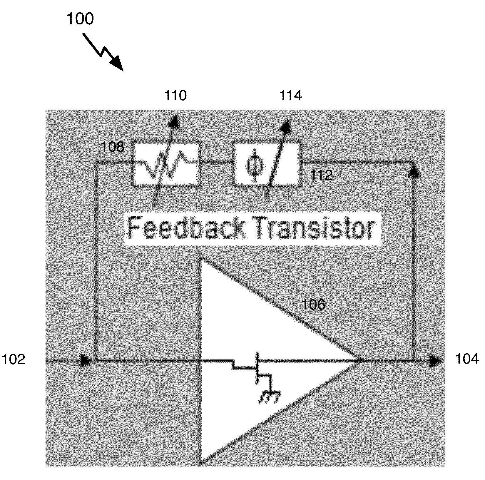
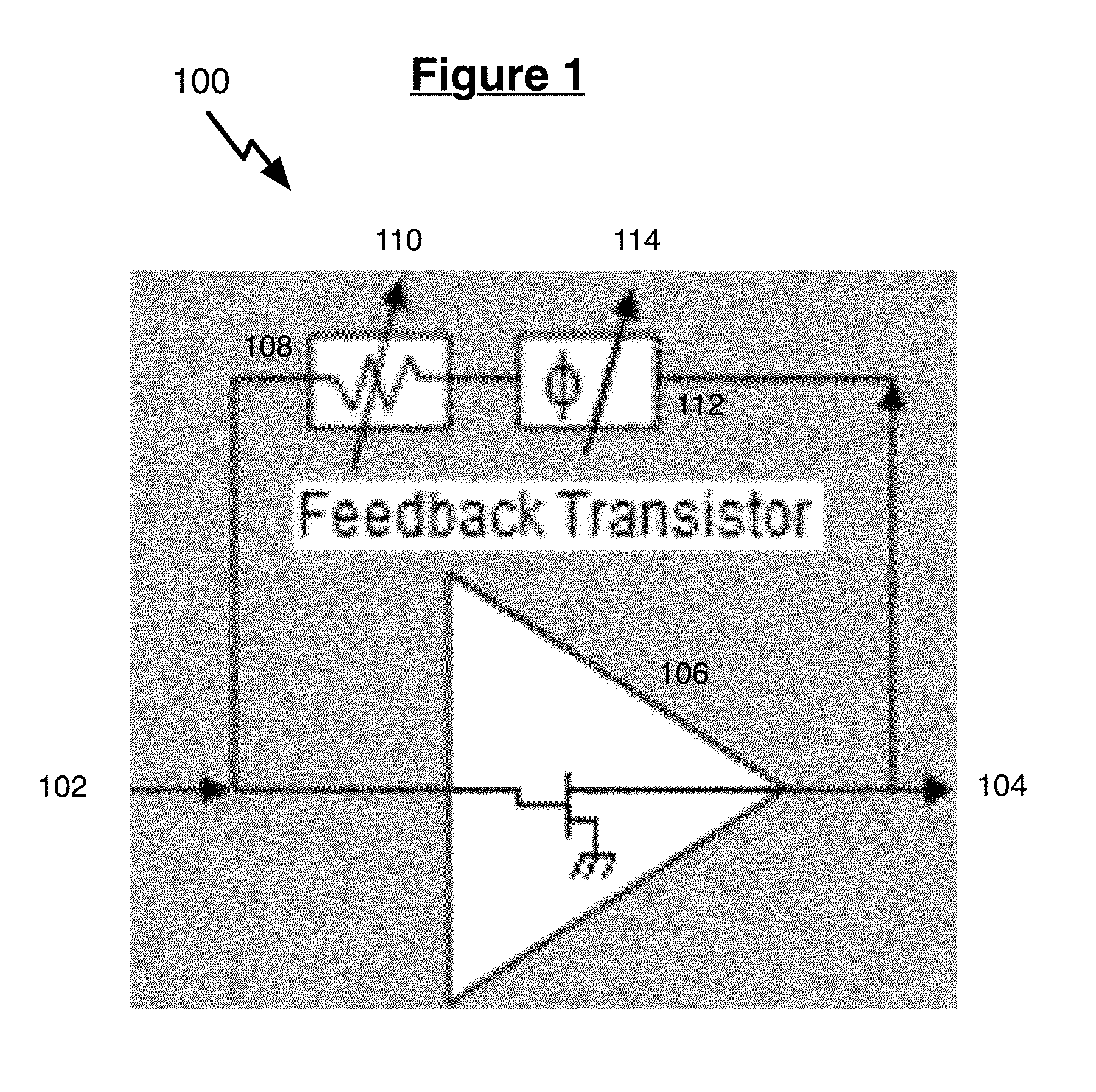
[0029]FIG. 1 shows an example of a circuit 100 for performing signal amplification. In circuit 100, amplifier 106 may be used to amplify input signals received via input port 102. The amplified signal may be received via output port 104. It is well known in the art that amplifiers often possess a linear range for amplification. For example, if input signals received by amplifier 106 via input port 102 are within such a linear range, then the amplified signal received via output port 104 will remain in linear proportion to the input signals (e.g., y=Gx, where y is the output signal, x is the input signal, and G is a constant gain factor supplied by amplifier 106). However, if such input signals exceed the linear range of amplifier 106, then the amplified signal received via output port 104 may exhibit nonlinear distortions.

[0030]For example, one nonlinear distortion is gain compression. As an input signal increases above the linear range, the ability of an amplifier to amplify the si...


PUM


Abstract

The present disclosure describes a method and system for linearizing an amplifier using transistor-level dynamic feedback. The method and system enables nonlinear amplifiers to exhibit linear performance using one or more of gain control elements and phase shifters in the feedback path. The disclosed method and system may also allow amplifiers to act as a pre-distorter or a frequency/gain programmable amplifier.

Description

CROSS-REFERENCE TO RELATED APPLICATIONS[0001]This application claims priority to U.S. Provisional Patent Appl. No. 61 / 929,015, filed on Jan. 18, 2014, the disclosure of which is incorporated herein in its entirety by reference.BACKGROUND[0002]1. Field of the Invention[0003]The present disclosure relates to a method and system for linearizing the performance of amplifiers using transistor-level dynamic feedback.[0004]2. Description of the Related Art[0005]Amplifiers are often treated as linear devices that amplify an input signal via a constant gain factor. It is well understood in the art that amplifiers often possess nonlinear performance above a certain threshold of input power. For example, as the power level of an input signal increases above such a threshold, an amplifier's ability to provide gain will often increasingly degrade. This can result in a distorted output signal from the amplifier due to the low-power elements of the input signal having been amplified with a higher ...

Claims


Application Information

Patent Timeline
IPC IPC(8): H03F1/32H03G3/30
CPCH03F1/3247H03G3/30H03F1/3252H03F2201/3212H03F2201/3233H03F2201/3231H03F2201/3227H03F1/3282H03F1/3288H03F1/56H03F3/193H03F3/245H03F2200/192H03F2200/204H03F2200/222H03F2200/318H03F2200/387H03F2200/411H03G1/0035H03G3/3036
Inventor DARWISH, ALI MOHAMED
Owner DARWISH ALI MOHAMED
Why Eureka
Try Eureka