Interface, communication apparatus, and program

US20150207913A1Active Publication Date: 2015-07-23MURATA MFG CO LTD

Image

  • Interface, communication apparatus, and program
  • Interface, communication apparatus, and program
  • Interface, communication apparatus, and program

Examples


first preferred embodiment

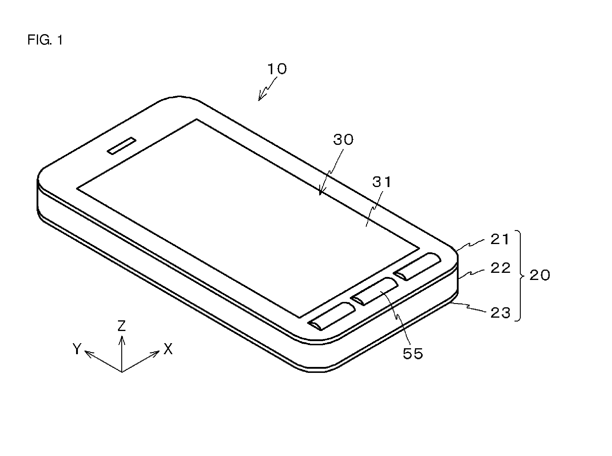
[0062]Hereinafter, a first preferred embodiment of the present invention will be described in detail with reference to the drawings. An XYZ coordinate system composed of mutually-orthogonal X, Y, and Z axes is used in the descriptions as appropriate.

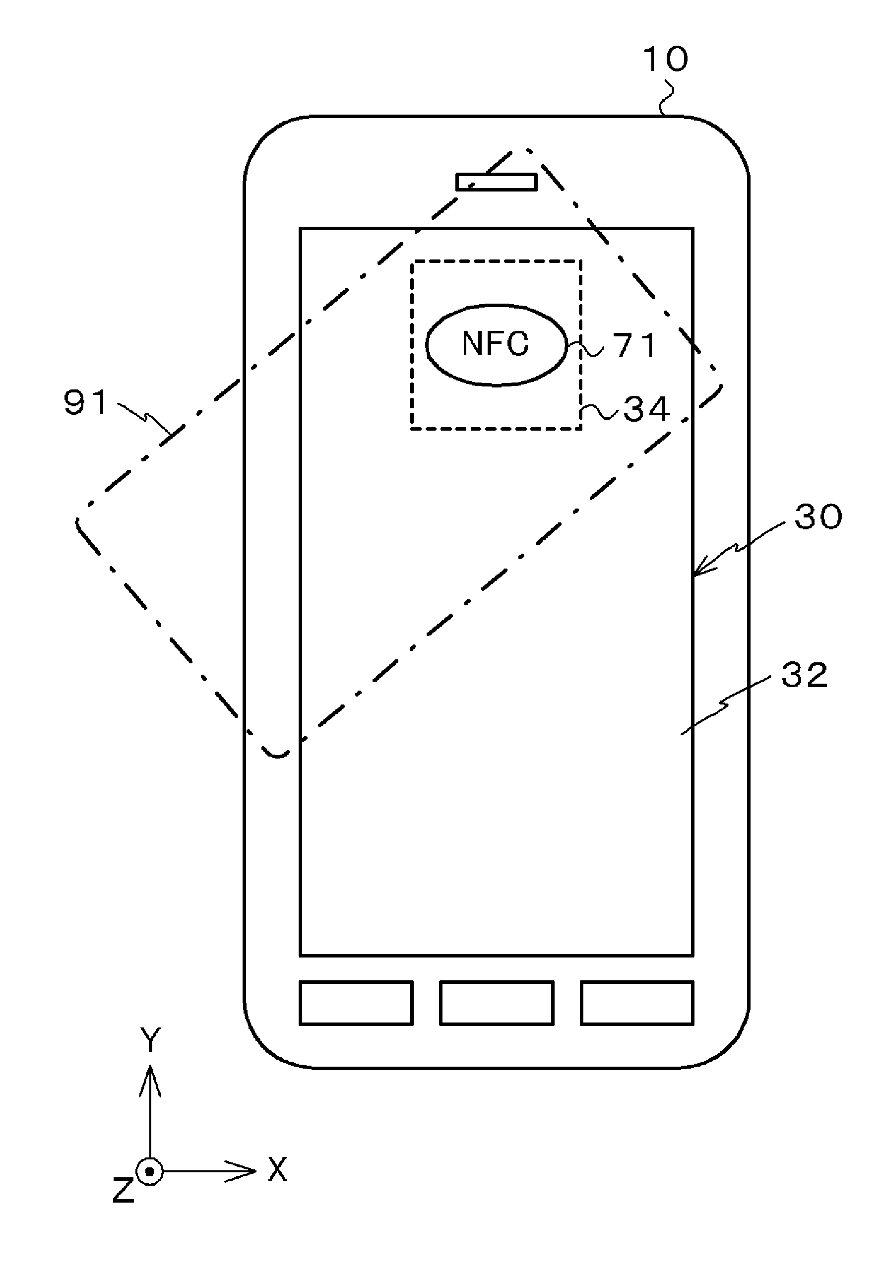
[0063]As illustrated in FIG. 1, a communication terminal 10 according to the present preferred embodiment preferably is a smartphone including an interface 30 contained within a housing 20. The interface 30 preferably is a touch panel-based graphical user interface.

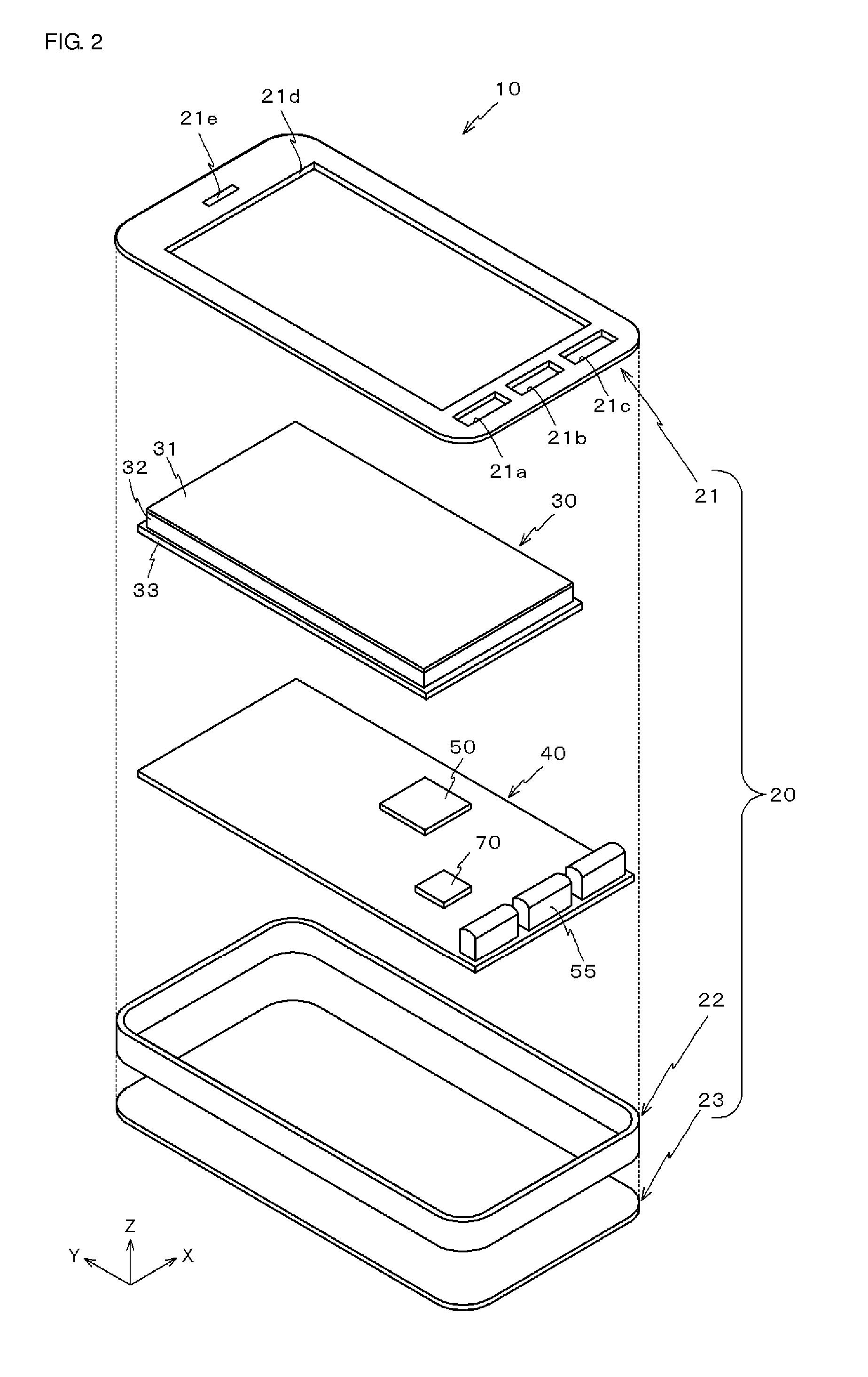
[0064]As illustrated in FIG. 2, the communication terminal 10 includes a front panel 21, a frame 22, and a rear panel 23 that configure the housing 20, as well as the interface 30 contained within the housing 20 and a control board 40.

[0065]The front panel 21 preferably is a rectangular or substantially rectangular panel whose longer direction matches the Y axis direction. A rectangular or substantially rectangular opening 21d that exposes the interface 30 is provided in the f...

second preferred embodiment

[0108]Next, a second preferred embodiment of the present invention will be described with reference to the drawings. Note that the same reference numerals are used for elements identical or corresponding to those of the first preferred embodiment.

[0109]As illustrated in FIG. 16, an interface 30A differs from the interface 30 according to the first preferred embodiment in that the power supply coil 34 is positioned between the display 32 and the shield plate 33.

[0110]The power supply coil 34 according to the present preferred embodiment includes a square main body portion 340a including the coil pattern 34a and a rectangular or substantially rectangular extending portion 340b extending from the main body portion 340a in the +Y direction. The extending portion 340b is flexible and therefore greatly deforms by bending or the like. The main body portion 340a includes the coil pattern 34a, and the extending portion 340b includes a lead wire that connects the coil pattern 34a to the RFIC ...


PUM


Abstract

A power supply coil is disposed on a rear surface of a display via a shield plate. When a current flows in the power supply coil, a magnetic flux emitted from the power supply coil traverses an opening of the shield plate. As a result, the power supply coil and the shield plate are electromagnetically coupled and the shield plate defines and functions as an antenna. Accordingly, a communication terminal communicates favorably with a smartcard, which is a device positioned on a front surface side of the display.

Description

BACKGROUND OF THE INVENTION[0001]1. Field of the Invention[0002]The present invention relates to interfaces, communication apparatuses, and programs.[0003]2. Description of the Related Art[0004]With the advancement of processors, communication terminals, as exemplified by cellular phones, are approaching the same level of functionality as personal computers. In particular, communication terminals that have GUIs (Graphical User Interfaces) are capable of providing interfaces to users to suit various purposes. For this reason, in addition to telephones, there are high expectations for the use of such interfaces in near-field communication compliant with the NFC (Near Field Communication) standard.[0005]To carry out near-field communication, it has thus far been necessary to bring an antenna disposed on a rear surface side of a communication terminal close to an external device serving as the subject for communication. A mark is therefore provided on the rear surface of the communicati...

Claims


Application Information

Patent Timeline
23 Jul 2015
Publication
US20150207913A1
IPC
H04M1/725; H04B5/02; H04W4/00; H04B5/00; H04M1/72412
CPC
H04M1/7253; H04B5/0037; H04W88/06; H04W4/008; H04B5/02; H01Q7/00; H01Q1/243; H04W4/80
Inventors
NAKANO, SHINICHI; MIURA, TEPPEI