
Implantable prosthesis for repairing or reinforcing an anatomical defect

a technology of anatomical defect and implantable prosthesis, which is applied in the field of implantable prosthesis, can solve the problems of difficult identification of body structures, undesirable procedures, and tendency for adhesions to form between these structures, and achieve the effect of stable deployment of implantable prosthesis

Active Publication Date: 2015-07-30
TYCO HEALTHCARE GRP LP
View PDF3 Cites 3 Cited by
  • Summary
  • Abstract
  • Description
  • Claims
  • Application Information

AI Technical Summary

Benefits of technology

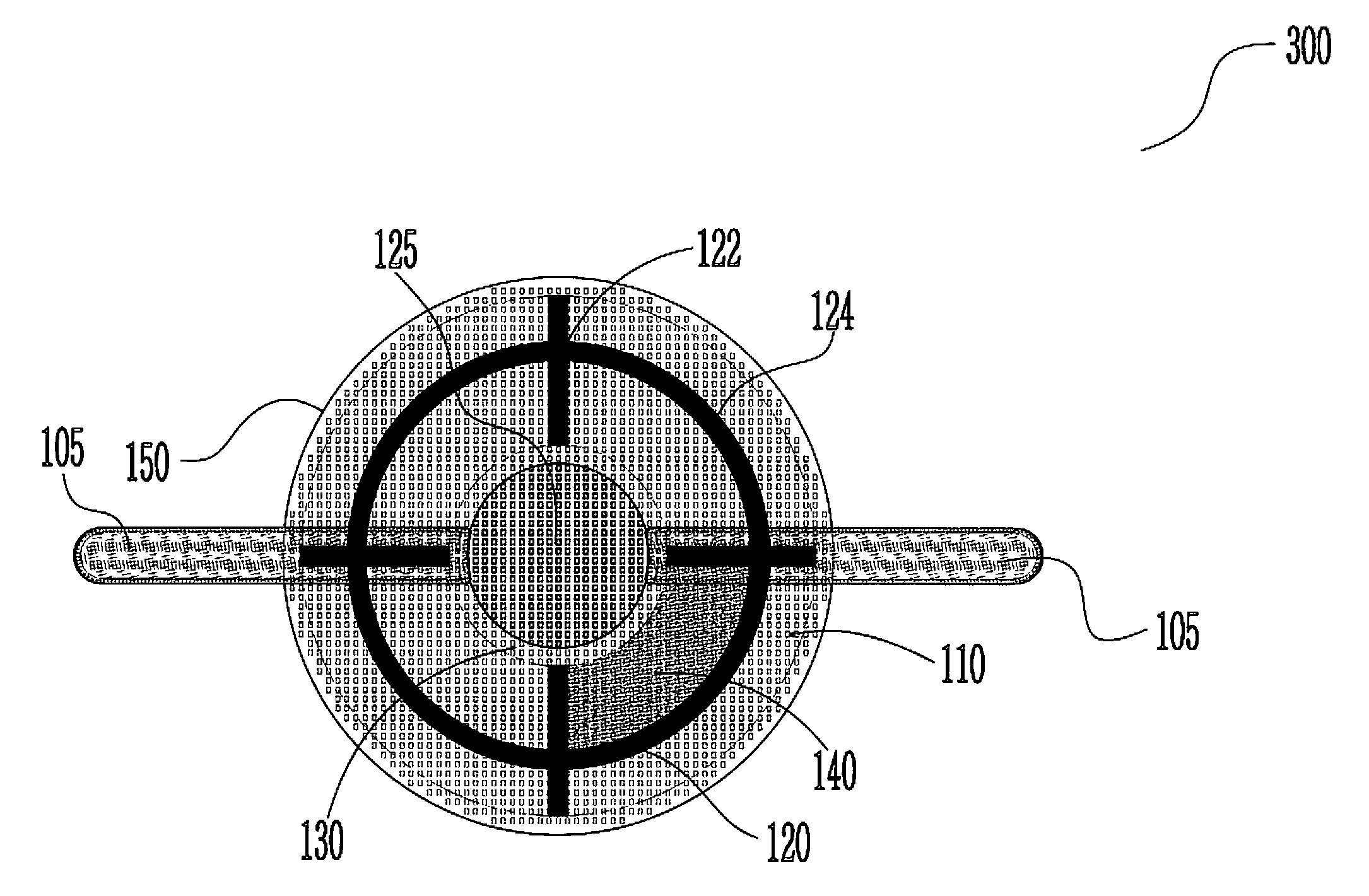
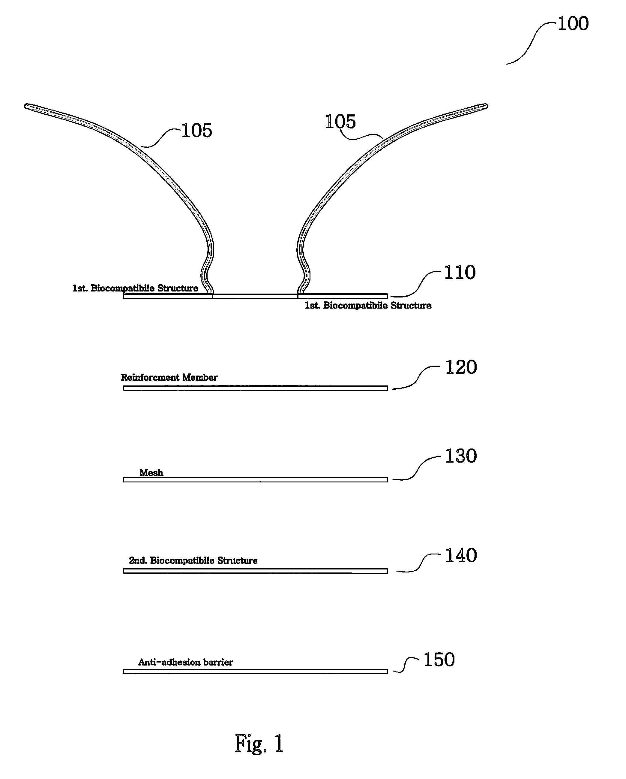
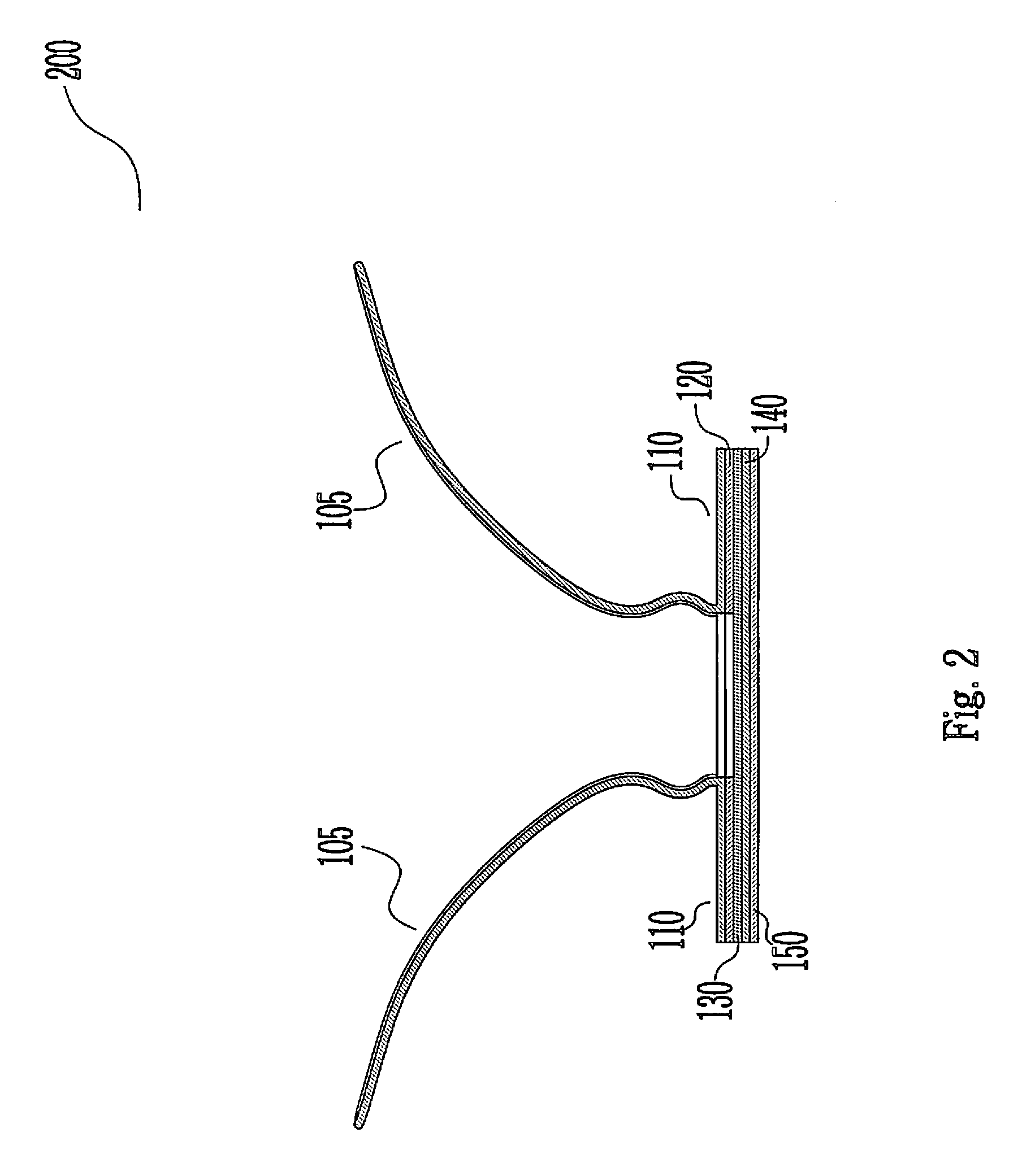
The patent describes an implantable prosthesis that includes a first biocompatible structure, a rigid reinforcement member, a mesh structure, a second biocompatible structure, and an anti-adhesion barrier. The rigid reinforcement member is made from an absorbable polymer material and has a plurality of openings and guide members molded on it. The mesh structure overlaps the inner circumferential ring of the rigid reinforcement member and promotes tissue ingrowth. The anti-adhesion barrier has a collagen coating. The technical effects of this invention are that it allows for stable deployment of the implantable prosthesis through an abdominal wall, provides reinforcement during surgery, and reduces adhesion to the abdominal wall.

Problems solved by technology

This often may be in an undesired plane, which can lead to bleeding which may obscure the field and make it difficult to identify the body structures.
Hernia repair using this procedure has a number of disadvantages, principally because the patch used for hernia repair is in direct contact with the structures in the abdominal cavity, as for example the intestines, so that there is a tendency for adhesions to form in between these structures.
Such a procedure is also undesirable because typically the patch is stapled into the peritoneum, which is a very thin unstable layer covering the inner abdomen.
This is time consuming and involves the risk of inadvertent cutting of important anatomic structures.

Method used


Image

  • Implantable prosthesis for repairing or reinforcing an anatomical defect
  • Implantable prosthesis for repairing or reinforcing an anatomical defect
  • Implantable prosthesis for repairing or reinforcing an anatomical defect

Examples


Embodiment Construction

[0026]Embodiments of the presently disclosed apparatus will now be described in detail with reference to the drawings, in which like reference numerals designate identical or corresponding elements in each of the several views. As used herein, the term “distal” refers to that portion of the tool, or component thereof which is further from the user while the term “proximal” refers to that portion of the tool or component thereof which is closer to the user.

[0027]While the use of the implantable prosthesis is often described herein as engaging an incision, it should be recognized that this is merely exemplary and is not intended to limit the use of the assembly in any way, but rather it should be recognized that the present disclosure is intended to be useable in all instances in situations in which the implantable prosthesis engages an incision, a naturally occurring orifice, or any other suitable opening.

[0028]Before explaining the present disclosure in detail, it should be noted th...


PUM


Abstract

An implantable prosthesis for repairing or reinforcing a tissue or muscle wall defect is provided. The implantable prosthesis includes a first biocompatible structure having a tether attached thereto for maintaining stable deployment of the implantable prosthesis through an abdominal wall; a rigid reinforcement member positioned adjacent a bottom side of the first biocompatible structure, the rigid reinforcement member including an inner circumferential ring, a plurality of spoke elements, a plurality of openings, and a plurality of guide members molded thereon; a mesh structure positioned adjacent a bottom surface of the rigid reinforcement member, the mesh structure overlapping the inner circumferential ring of the rigid reinforcement member; a second biocompatible structure and an anti-adhesion barrier having a collagen coating positioned on a bottom surface of the second biocompatible structure.

Description

CROSS REFERENCE TO RELATED APPLICATION[0001]The present application claims the benefit of and priority to U.S. Provisional Application Ser. No. 61 / 541,551, filed on Sep. 30, 2011, the entire contents of which are incorporated herein by reference.BACKGROUND[0002]1. Technical Field[0003]The present disclosure relates to implantable prostheses. More particularly, the present disclosure relates to an implantable prosthesis for repairing and / or reinforcing an anatomical defect.[0004]2. Background of Related Art[0005]In the past, in developing spaces and potential spaces within a body, blunt dissectors or soft-tipped dissectors have been utilized to create a dissected space which is parallel to the plane in which the dissectors are introduced into the body tissue. This often may be in an undesired plane, which can lead to bleeding which may obscure the field and make it difficult to identify the body structures.[0006]In utilizing such apparatus and methods, attempts have been made to deve...

Claims


Application Information

Patent Timeline
Patent Type & Authority Applications(United States)
IPC IPC(8): A61F2/00
CPCA61F2210/0076A61F2/0063A61F2250/0051A61F2250/0039A61F2250/0018A61F2/0077A61F2002/009
Inventor COHEN, MATTHEW D.
Owner TYCO HEALTHCARE GRP LP
Learn More