Multi-channel pyrolysis tubes, material deposition equipment including the same and associated methods

a technology of pyrolysis tubes and material deposition equipment, which is applied in the direction of hydrocarbon by depolymerisation, hydrocarbon by polyarylsubstituted aliphatic compound split-off, organic chemistry, etc., can solve the problem of inefficiency of parylene dimers, reduce the overall duration of time needed to deposit parylene films of any desired thickness, and reduce the time required to effectively pyrolyze parylene dimers. , the effect o

Inactive Publication Date: 2015-07-30
HZO INC
View PDF7 Cites 3 Cited by
  • Summary
  • Abstract
  • Description
  • Claims
  • Application Information

AI Technical Summary

Benefits of technology

[0012]A pyrolysis tube configured in accordance with teachings of this disclosure may enable pyrolysis to occur efficiently at a lower-than-conventional temperature (e.g., a temperature of less than 680° C., a temperature of 550° C. to 680° C., a temperature of less than 550° C., a temperature of less than 500° C., a temperature of about 400° C. to about 450° C., etc.). Such a configuration may also facilitate the use of smaller, or shorter, pyrolysis tubes. In addition, such a configuration may decrease the time required to effectively pyrolyze a parylene dimer and, thus, decrease the overall duration of time needed to deposit a parylene film of any desired thickness onto a substrate. By enabling the use of lower pyrolysis temperatures and increasing the efficiency with which parylene dimers are pyrolyzed, uniformity or substantially uniformity of the temperature across the primary passage through the pyrolysis tube may also decrease the frequency with which the pyrolysis tube or elements downstream from the pyrolysis tube are cleaned.
[0013]In another aspect, a material deposition system or another embodiment of material processing equipment may include a pyrolysis tube according to this disclosure. In some embodiments, the material processing equipment may comprise conventional material processing equipment with a conventionally configured pyrolysis tube. An insert for the pyrolysis tube may be configured to impart the pyrolysis tube with a plurality of channels. The insert may be configured to be introduced into and removed from a primary conduit of the conventionally configured pyrolysis tube. The use of an insert with a conventionally configured pyrolysis tube of conventional material processing equipment may improve the efficiency with which the pyrolysis tube pyrolyzes precursor material, enable the conventional material processing equipment to complete pyrolysis in a reduced duration of time and / or enable the conventional material processing equipment to operate at a reduced pyrolysis temperature.
[0014]In embodiments where the insert is configured to be removed from the pyrolysis tube, removability of the insert may enable inserts with a plurality of different configurations to be used with the same pyrolysis tube, as well as cleaning of the insert and / or the pyrolysis tube.

Problems solved by technology

Pyrolysis of pure parylene dimers is typically considered to be a highly efficient process; however, since some contaminants are typically present in the parylene precursor, and possibly because pyrolysis tubes are rarely totally devoid of oxygen, the process of cracking parylene dimers can be inefficient, undesirably slow and result in byproducts that must be occasionally cleaned from the pyrolysis tube and other parts of the deposition equipment of which the pyrolysis tube is a part.
In addition, such a configuration may decrease the time required to effectively pyrolyze a parylene dimer and, thus, decrease the overall duration of time needed to deposit a parylene film of any desired thickness onto a substrate.

Method used


Image

  • Multi-channel pyrolysis tubes, material deposition equipment including the same and associated methods
  • Multi-channel pyrolysis tubes, material deposition equipment including the same and associated methods
  • Multi-channel pyrolysis tubes, material deposition equipment including the same and associated methods

Examples


Embodiment Construction

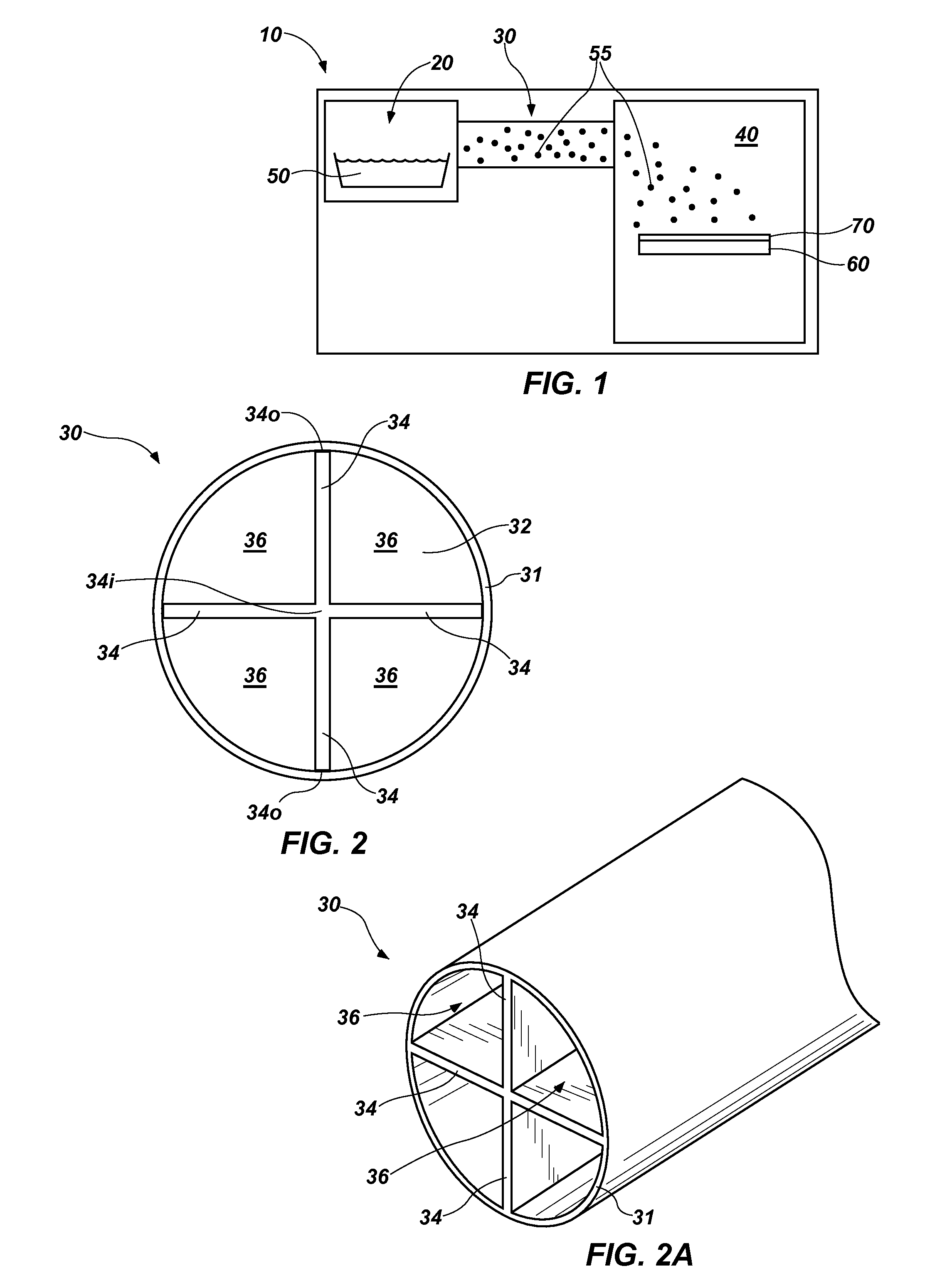
[0025]With reference to FIG. 1, a schematic representation of a material deposition system 10 is illustrated. The depicted embodiment of material deposition system 10 includes a pyrolysis tube 30 and a deposition chamber 40 downstream from the pyrolysis tube 30. Additionally, the material deposition system 10 may include a volatilization element 20, such as a vaporization chamber, upstream from the pyrolysis tube 30.

[0026]In use, the material deposition system 10 may be configured to receive a precursor material 50, convert the precursor material 50 to reactive species 55 and provide an environment in which molecules of the reactive species 55 may react with one another to form a polymer film 70 on one or more substrates 60. In the specific embodiment depicted by FIG. 1, a precursor material 50, such as a substituted or unsubstituted parylene dimer (e.g., [2.2]paracyclophane, etc.), may be placed in the volatilization element 20 of the material deposition system 10. The volatilizati...


PUM

PropertyMeasurementUnit
temperatureaaaaaaaaaa

Abstract

A pyrolysis tube for use with a material deposition system includes a plurality of channels. The channels may be defined by internal elements of the pyrolysis tube, or by internal elements that form an insert for a conventionally configured pyrolysis tube. One or more of the channels may extend straight through the pyrolysis tube, providing a direct line of sight through the pyrolysis tube. Material deposition systems that include such an insert or pyrolysis tube are also disclosed, as are methods for efficiently pyrolyzing precursor materials at temperatures that are reduced relative to conventional pyrolysis temperatures and/or at rates that are increased relative to conventional pyrolysis rates.

Description

CROSS-REFERENCE TO RELATED APPLICATION[0001]A claim for priority to the Jan. 28, 2014 filing date of U.S. Provisional Patent Application No. 61 / 932,774, titled PYROLYSIS TUBE INCLUDING ONE OR MORE BAFFLES (“the '774 Provisional application”) is hereby made pursuant to 35 U.S.C. §119(e). The entire disclosure of the '774 Provisional application is hereby incorporated herein.TECHNICAL FIELD[0002]This disclosure relates generally to pyrolysis tubes for material processing equipment (e.g., material deposition systems, etc.) and, more specifically, to pyrolysis tubes that are configured to improve the efficiency with which molecules of a precursor material are broken down, or “cracked,” into smaller reactive species. In addition, this disclosure relates to inserts for pyrolysis tubes, pyrolysis methods and equipment for depositing or otherwise processing materials, such as parylene.RELATED ART[0003]Pyrolysis is a process by which an organic material is subjected, in an environment devoid...

Claims


Application Information

Patent Timeline
Patent Type & Authority Applications(United States)
IPC IPC(8): C23C16/452C07C4/22
CPCC07C4/22C23C16/452C23C16/30B05D1/60C07C4/24C07C15/08B01J19/2415B01J2219/00087B01J2219/24C23C16/455
Inventor DEMPSTER, JAMESMAYNARD, JASON
Owner HZO INC
Why Eureka
Try Eureka