
Manual measuring system

Active Publication Date: 2015-07-30
MITUTOYO CORP
View PDF12 Cites 21 Cited by
  • Summary
  • Abstract
  • Description
  • Claims
  • Application Information

AI Technical Summary

Benefits of technology

The present invention provides a solution for improving the efficiency and accuracy of measuring in a manual measuring system by incorporating a sub-monitor mounted near the tip of a measuring probe. The sub-monitor can display a guided route for the measuring probe to a measurement point, and can also display the content of the control software. The sub-monitor can be a touch panel display or a portable terminal, and can be mounted close at hand or detachable from the manual measuring system. The invention allows the user to check the information of the control software without interrupting the measurement, and can improve the quality and efficiency of the measurement process. It can also improve usability and convenience by allowing the user to operate the control software with one hand and provide a better view of the work by using the sub-monitor.

Problems solved by technology

However, it is a significant drawback with this system that the user U is expected to direct the line of sight to the display 32 of the desktop computer 30.
However, in most cases, since the line of sight is still deviated, measurements are interrupted to view the details being displayed.
This leads to the same problem as that with the desktop computer.
However, even in the technique disclosed in Patent Literature 3, since the text screen is mounted on the arm tip, appropriate navigation or measurement instructions could not be provided.
For example, there was also a problem that test gages and test jigs used for automobiles parts were used to measure a designated point; however, as illustrated in FIG. 3, the user could not locate the actual position on the work W, and it was thus difficult to measure the designated point with the articulated three-dimensional coordinate measuring machine.

Method used


Image

  • Manual measuring system
  • Manual measuring system
  • Manual measuring system

Examples


first embodiment

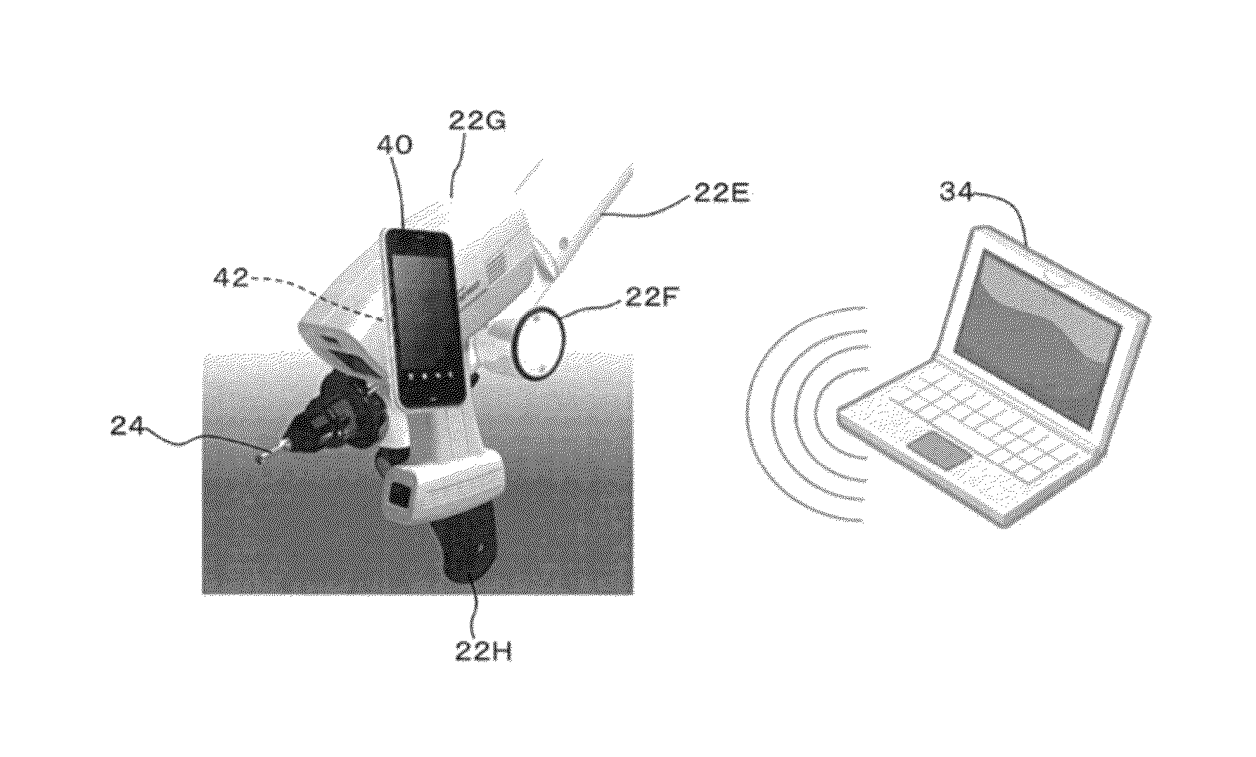
[0051]the present invention is the aforementioned articulated three-dimensional coordinate measuring machine 20 to which the present invention is applied. That is, as illustrated in detail inFIG. 5, a portable terminal (so-called smartphone) 40 having a touch panel display is mounted as a sub-monitor near the tip of the measuring probe 24 via an angle-variable link mechanism 42 illustrated in FIG. 6.

[0052]The link mechanism 42 enables the user U to adjust the position and angle of the portable terminal 40 during a measurement and improves the visibility of the portable terminal 40 and the point of measurement. Note that the link mechanism 42 may also be omitted.

[0053]The portable terminal 40 is connected to a desktop computer or a notebook PC 34 in wired or wireless communication therewith and functions to allow measurement information transmitted by control software of the notebook PC 34 to be displayed as text data or graphic data on the portable terminal 40 or informed by sound o...

second embodiment

[0066]Now, a description will be made to a gantry manual three-dimensional coordinate measuring machine according to the present invention.

[0067]As illustrated in FIG. 10, the gantry three-dimensional coordinate measuring machine 50 includes: a table 52 on which a work W is placed; a gantry frame 54 which is movable in the depth direction (Y direction) of the figure relative to the table 52; an X-axis slider 56 which is movable from side to side (in the X direction) of the figure on the gantry frame 54; a Z-axis spindle 58 which is movable in the vertical direction (Z direction) of the figure on the X-axis slider 56; and a measuring probe 60 secured to the tip (the lower end in the drawing) of the Z-axis spindle 58. The measuring machine 50 is configured to measure the shape of the work W by manually moving the measuring probe 60.

[0068]The gantry frame 54, the X-axis slider 56, and the Z-axis spindle 58 each include a built-in linear encoder (not illustrated) for detecting positions...

third embodiment

[0072]Furthermore, as illustrated in FIG. 12 as a third embodiment, the portable terminal 40 may be made detachable from the measuring machines 20 and 50. In the drawing, FG denotes a common front glass (windshield) to be measured. In this case, the portable terminal 40 may be removed from one measuring machine (20 in the drawing) and then attached to the other measuring machine (50 in the drawing) so as to be connected to a control PC of the measuring machine 50. It is thus possible to share the portable terminal 40 among the plurality of measuring machines 20 and 50. If wired, the portable terminal 40 is connected or disconnected only when being attached or detached (a pairing operation is required in case of wireless Bluetooth (trade mark)), allowing one portable terminal 40 to hold the states of the plurality of measuring machines 20 and 50. For example, to compare the measurement results of the measuring machine 20 with the measurement results of the measuring machine 50, what ...


PUM


Abstract

A manual measuring system (an articulated three-dimensional coordinate measuring machine or a gantry three-dimensional coordinate measuring machine) allows a measuring probe to be manually moved while enabling a user to focus on making measurements and allows the user to manually move the measuring probe in order to facilitate and accelerate measurements. The manual measuring system includes a sub-monitor (portable terminal) that is mounted near the tip of the measuring probe. It is possible to display on the sub-monitor a guided route for the measuring probe to a measurement point or to indicate on the sub-monitor that the measuring probe has entered a measurement allowable range or to allow the user to direct by means of the sub-monitor to obtain a measurement value by the measuring probe.

Description

CROSS-REFERENCE TO RELATED APPLICATION[0001]The disclosure of Japanese Patent Application No. 2014-014979 filed on Jan. 29, 2014 including specifications, drawings and claims is incorporated herein by reference in its entirety.TECHNICAL FIELD[0002]The present invention relates to manual measuring systems, and more particularly, to a manual measuring system which allows a measuring probe to be manually moved and which is preferred for use with a manual three-dimensional coordinate measuring machine.BACKGROUND ART[0003]As illustrated by an articulated three-dimensional coordinate measuring machine 20 in FIG. 1, Japanese Patent Application Laid-Open No. 2007-47014 (hereafter, Patent Literature 1) discloses a manual three-dimensional coordinate measuring machine in which a measuring probe 24 disposed at the tip of an arm mechanism 22 is manually moved. This measuring machine allows the user to measure a work W in a contact or noncontact manner by the measuring probe 24 while referring t...

Claims


Application Information

Patent Timeline
IPC IPC(8): G01B21/04
CPCG01B21/04G01B5/008G01B21/047
Inventor ABE, SHINSAKUSUZUKI, KOZABURO
Owner MITUTOYO CORP
Features
  • Generate Ideas
  • Intellectual Property
  • Life Sciences
  • Materials
  • Tech Scout
  • Unparalleled Data Quality
  • Higher Quality Content
  • 60% Fewer Hallucinations
Learn More