GPS arrival angle selecting system and method

a technology of arrival angle and selecting system, which is applied in the direction of multi-channel direction-finding system using radio waves radio wave direction/deviation determination system, etc., can solve the problem of serious problems in estimating a gps arrival angle, inability to estimate and difficulty in accurately estimating the gps arrival angle information, etc. problem, to achieve the effect of improving the performance of the g

Active Publication Date: 2015-07-30
IND ACADEMIC CORP FOUND YONSEI UNIV
View PDF6 Cites 15 Cited by
  • Summary
  • Abstract
  • Description
  • Claims
  • Application Information

AI Technical Summary

Benefits of technology

[0010]The GPS arrival angle selecting system according to the present invention can select an arrival angle of an accurate GPS signal by comparing arrival angles estimated by signals before and after despreading. Moreover, it is possible to enhance the performance of a GPS receiver under a high-power interference environment.

Problems solved by technology

Since the electric power of a GPS signal is far lower than the high noise power level and the high interference signal electric power, it is quite difficult to estimate accurate GPS arrival angle information.
While the conventional arrival angle estimation algorithms are superior in arrival angle estimation performance, they have serious problems in estimating a GPS arrival angle.
This makes it impossible to estimate the GPS arrival angle.

Method used


Image

  • GPS arrival angle selecting system and method
  • GPS arrival angle selecting system and method
  • GPS arrival angle selecting system and method

Examples


Embodiment Construction

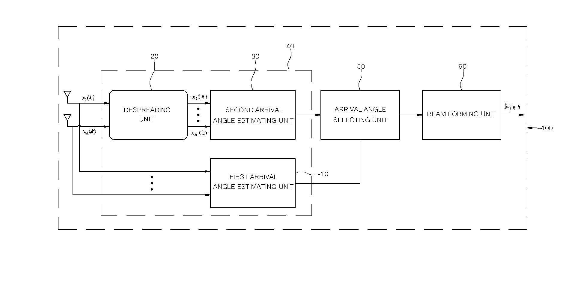
[0020]Certain preferred embodiments of a GPS arrival angle selecting system and method according to the present invention will now be described in detail with reference to the accompanying drawings.

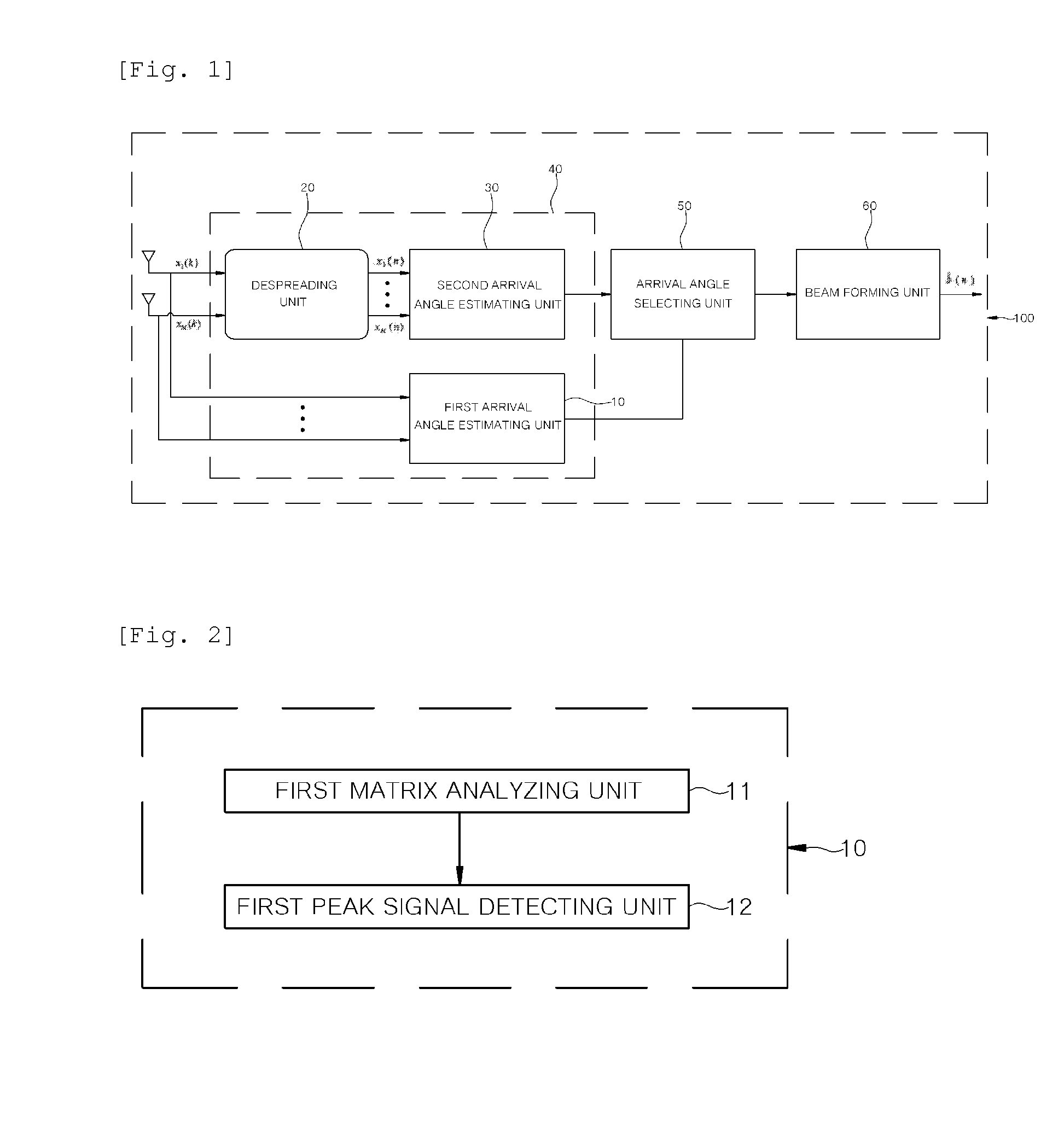
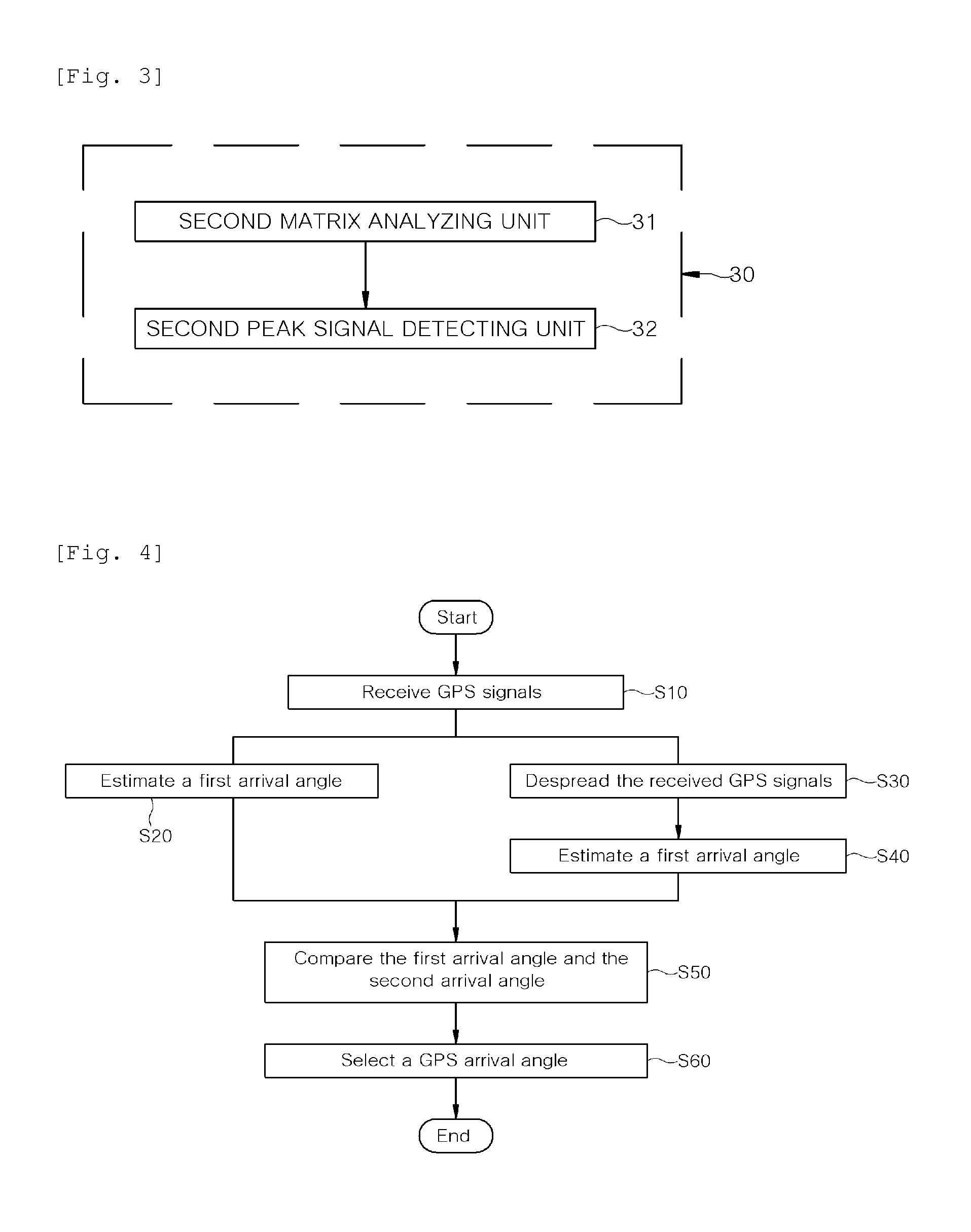
[0021]FIG. 1 is a block diagram showing the overall configuration of a GPS arrival angle selecting system 100 according to the present invention. The GPS arrival angle selecting system 100 includes an arrival angle estimating unit 40, an arrival angle selecting unit 50 and a beam forming unit 60.

[0022]The GPS arrival angle selecting system 100 takes into account the arrival angle selection with respect to the C / A (Coarse Acquisition). In a GPS receiver including M antenna array elements, the received signal vector (magnitude M) at sample index k is given by equation 1:

x(k)=acci(k)b(k)+As(k)+v(k),

where i denotes a satellite index, and other variables are summarized in Table 1 below.

TABLE 1SymbolsDefinitionacArray response vector (magnitude M) to a GPS signalci(k)Cyclostationary PRN code el...


PUM


Abstract

Disclosed is a GPS arrival angle selecting system. The system includes: a arrival angle estimating unit connected to a receiving antenna of a GPS receiver including at least one antenna array element and configured to decide a first arrival angle of a signal received prior to despreading and a second arrival angle of a signal received after despreading; and an arrival angle selecting unit configured to select a different peak value by comparing the first arrival angle and the second arrival angle. Also disclosed is a GPS arrival angle selecting method.

Description

FIELD OF THE INVENTION[0001]The present invention relates to a technology for estimating an arrival angle of a GPS (Global Positioning System) designed to determine the position of a person or an object and, more particularly, to a GPS arrival angle selecting system and method capable of selecting an arrival angle of an accurate GPS signal by comparing a pre-despreading arrival angle with a post-despreading arrival angle.BACKGROUND ART[0002]In general, a GPS satellite utilizing a low-power direct-sequence spread spectrum (DSSS) signal transmits two types of signals, namely an L1 signal having a carrier frequency of 1574.42 MHz and an L2 signal having a carrier frequency of 1227.60 MHz. A modernized GPS additionally utilizes two commercialized signals, namely an L2c signal having a carrier frequency of 1227.60 MHz and an L5 signal having a carrier frequency of 1176.45 MHz.[0003]Most beam formers for a GPS antenna employing conventional multiple antenna elements require accurate GPS a...

Claims


Application Information

Patent Timeline
Patent Type & Authority Applications(United States)
IPC IPC(8): G01S19/24G01S3/14
CPCG01S3/14G01S19/24G01S3/74G01S19/21G01S19/35
Inventor HWANG, SUK-SEUNG
Owner IND ACADEMIC CORP FOUND YONSEI UNIV
Why Eureka
Try Eureka