Voltage Limiting Device for Use in a Distributed Control System

a technology of distributed control and voltage limit, which is applied in the direction of electric variable regulation, process and machine control, instruments, etc., can solve the problems of limited power available in the system, insufficient operation of all field devices in the system, and limit the amount of energy available to spurs, so as to reduce the number of products a customer and simplify segment design

Active Publication Date: 2015-07-30
PHOENIX CONTACT DEVMENT & MFG
View PDF8 Cites 6 Cited by
  • Summary
  • Abstract
  • Description
  • Claims
  • Application Information

AI Technical Summary

Benefits of technology

[0023]Placing voltage limitation at the spur circuits does not create a single point of failure in the control network or the device segment as does placing voltage limitation for the entire system at the power conditioner. Integrating the voltage limiting device into a device coupler, furthermore, reduces the number of products a customer must procure and simplifies segment design.

Problems solved by technology

Field devices may be located in hazardous areas of the plant that present the risk of fire.
A problem with an intrinsically safe control system is that the limited power available in the system may be insufficient to operate all the field devices in the system, including those in safe areas.
The barrier provides a limited number of spurs that extend into the hazardous area, and limits the amount of energy available to the spurs.
(a) because the intrinsic safety concept begins at the power conditioner, all equipment connected to the trunk circuit must be limited in accordance with intrinsic safety standards;
(b) intrinsically safe terminals must be physically separated from all non-intrinsically safe terminals. This requirement typically must be observed for all trunk connections, including the power conditioner and any other equipment attached to the trunk circuit;
(c) intrinsically safe signals are not to be carried in the same cable as non-intrinsically safe signals. Trunk circuits are often included as part of multi-core cabling, limiting the use of the other cabling lines; and
(d) the lower the output voltage of a power conditioner, the shorter the maximum length of the trunk circuit. Device loading on the segment and cable resistance per unit length limit the maximum trunk circuit length. For example, the maximum voltage of a Fieldbus intrinsically safe power conditioner is typically set to 24 volts because the majority of intrinsically safe field devices are limited to a maximum input voltage of 24 volts. The maximum length of a trunk circuit is significantly shortened as compared to a trunk circuit operating at a higher maximum voltage under normal segment loading conditions.

Method used


Image

  • Voltage Limiting Device for Use in a Distributed Control System
  • Voltage Limiting Device for Use in a Distributed Control System
  • Voltage Limiting Device for Use in a Distributed Control System

Examples


Embodiment Construction

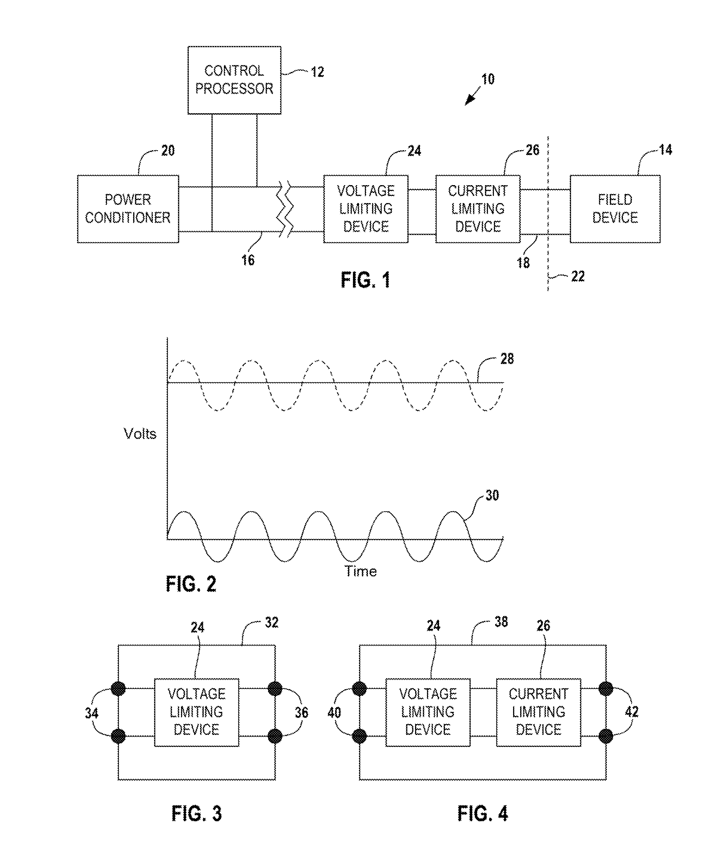
[0052]FIG. 1 illustrates a distributed control system 10 that includes a control processor 12 that transmits and receives AC data signals to and from a field device 14. The control processor 12 is connected to a trunk circuit 16 and the field device 14 is connected to a spur circuit 18 connected to the trunk circuit 16 (to simplify the drawing, the control system 10 is shown as having only one field device 14). The trunk circuit 18 also transmits DC power supplied through a power conditioner 20 to the spur circuit 18 to power the field device 14.

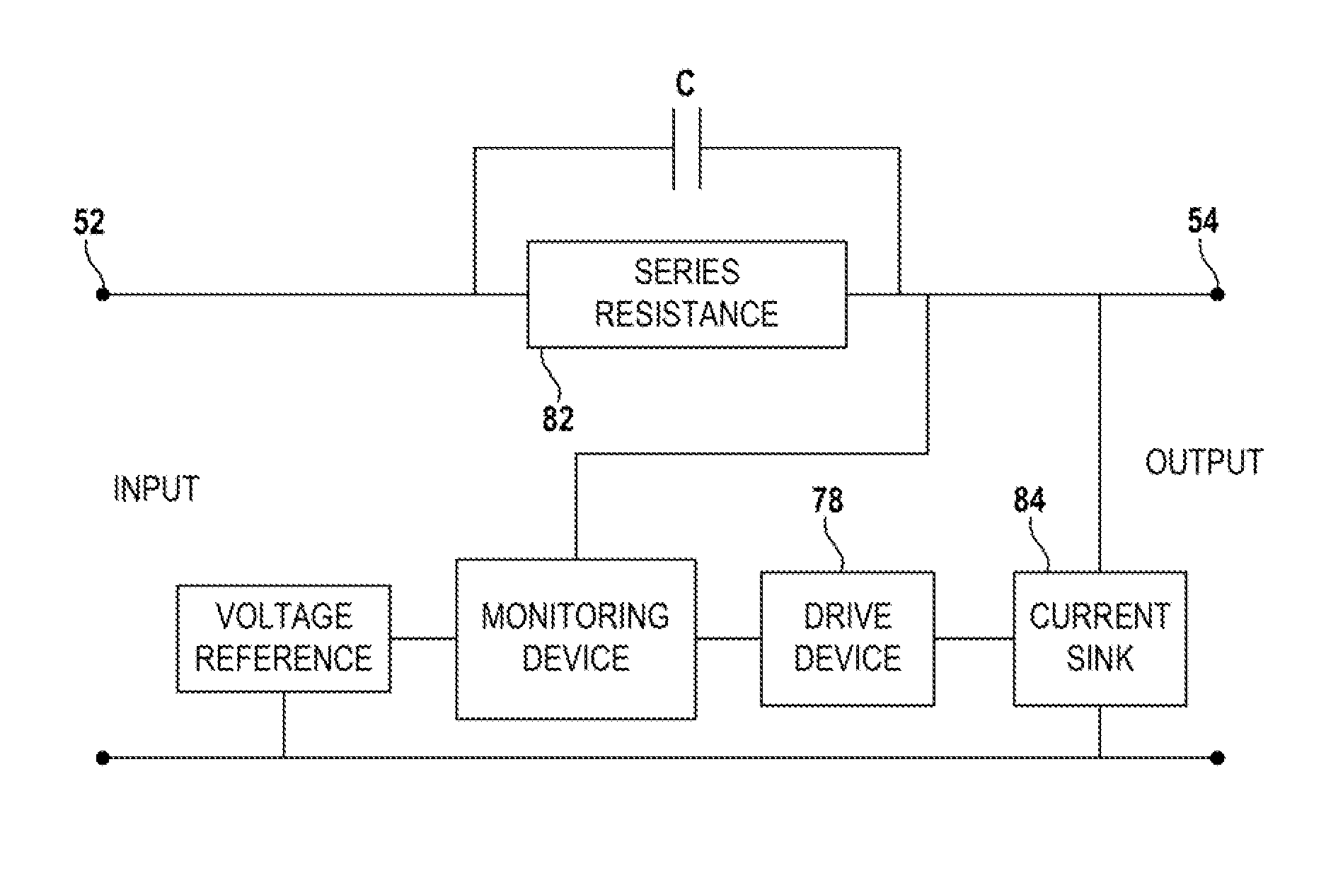
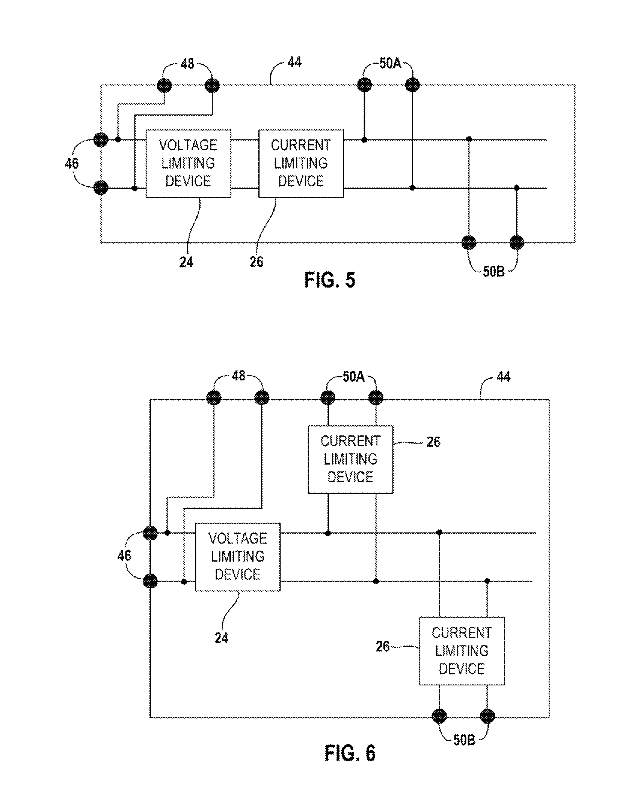
[0053]The field device 14 is shown in a Division 2 (Zone 2) hazardous area. The dividing line between the hazardous area and the safe area is represented by the dashed line 22. The spur line 18 extends from the safe area into the hazardous area. A voltage limiting device 24 and a current limiting device 26 are located in the safe area in series between the trunk circuit 16 and the spur circuit 18. The voltage limiting device 24 and the curre...


PUM


Abstract

A voltage limiting device for limiting the voltage being transferred from a trunk circuit to a spur circuit of a distributed control network includes an AC signal device that passes the AC data signals between the trunk circuit and the spur circuit.

Description

FIELD OF THE DISCLOSURE[0001]The disclosure relates to a control system for real-time distributed control, and more specifically, to a voltage limiting device usable in providing an inherently safe interface between a trunk circuit and spur circuits of the control system.BACKGROUND OF THE DISCLOSURE[0002]Automated industrial systems have field devices that monitor, control, and operate an industrial process. The field devices communicate with a control processor through a trunk circuit that transmits DC voltage through a power conditioner to power the field devices and transmits AC voltage data signals (which can include operating commands) superimposed on the DC voltage bi-directionally between the control processor and the field devices.[0003]The field devices can be distributed throughout the industrial plant, and the data transmittal rates allow essentially real-time control of the process. Field devices each attach to the trunk circuit via a spur or drop circuit. The trunk circ...

Claims


Application Information

Patent Timeline
Patent Type & Authority Applications(United States)
IPC IPC(8): G05F1/56H02H9/00
CPCH02H9/00G05F1/56G05F1/613H02H9/008
Inventor CHEREWKA, MICHAEL COLINHELFRICK, BRENTON EUGENEKREIDER, AARON RICHARD
Owner PHOENIX CONTACT DEVMENT & MFG
Why Eureka
Try Eureka